
Field serviceable electronic display

a technology of electronic display and field service, applied in the field of electronic display, can solve the problems of failure or deformation of performance, high cost and time-consuming process of replacing any failed electronic assembly, and the inability to remove the display, so as to reduce the amount of time required to access the display, reduce the interruption of traffic (both human, auto, rail) and reduce the effect of loss of value advertising revenu

Active Publication Date: 2011-05-19
MFG RESOURCES INT INC
View PDF60 Cites 114 Cited by
  • Summary
  • Abstract
  • Description
  • Claims
  • Application Information

AI Technical Summary

Benefits of technology

[0008]An exemplary display can be serviced quickly, by minimally-trained personnel while the display remains in its mounted position. The end user may even service the display themselves. Especially in advertising, when displays are inoperable or malfunctioning, valuable advertising revenue can be lost. By reducing the amount of time required to access a display, any interruption of traffic (both human, auto, and rail) may be minimized.

Problems solved by technology

Displays which can provide these features typically contain a number of advanced electronic assemblies, which over time, can fail or degrade in performance.
Once these displays are mounted in the user's desired position, replacing any failed electronic assemblies can be a costly and time-consuming process.
Removing the display can be very expensive and time consuming, especially in highly trafficked and difficult-to-access areas.
Further, replacement of certain parts may require a ‘clean room’ environment.
Typically, the replacement of many electronic assemblies requires access to the rear of the display, which is often used as the mounting surface for the display (thus limiting access to the rear of the display).
In many applications, electronic displays may be mounted side-by-side in an array, where access to the right or left (or both) sides of the display is also limited.
Further, in some applications a display may be mounted near overhead obstacles such as lights, ceilings, and overhangs where access to the top of the display is also limited.
Further, in some applications a pair of displays may be mounted back-to-back so that access to the rear of the display is limited due to the presence of the other display.

Method used


Image

  • Field serviceable electronic display
  • Field serviceable electronic display
  • Field serviceable electronic display

Examples


Embodiment Construction

)

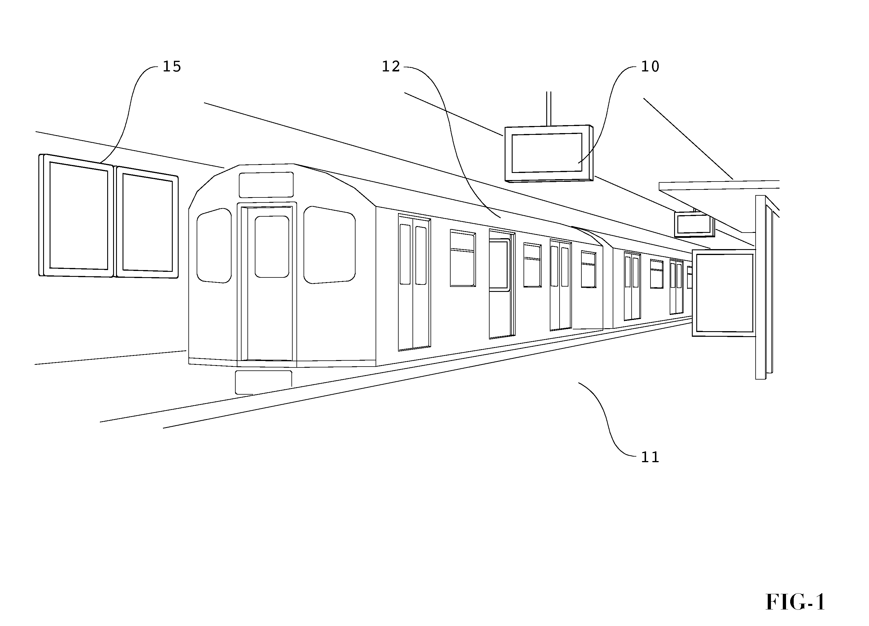
[0021]FIG. 1 provides an illustration of several possible placement positions for modern electronic displays. The particular illustration shown in this figure is a transit station (ex. light rails, subways, passenger trains). Display 10 is mounted above the platform 11 and adjacent to the train 12. As can be readily appreciated, display 10 is located in a highly-trafficked area so that its visibility to consumers remains high. However, to remove the display 10 from its mounted position in order to service the display 10 would result in a lengthy disruption of the human traffic below. This disruption would be repeated when the display 10 is again remounted (or replaced). Some displays can be very heavy (150-400 lbs for example) and can be very difficult to remove from their mounting and / or re-mount. Further, the lengthy downtime while the display 10 is being repaired / replaced would result in a loss of valuable advertising revenue. Alternatively, if the display 10 is being used for i...


PUM

PropertyMeasurementUnit
Forceaaaaaaaaaa
Interfaceaaaaaaaaaa

Abstract

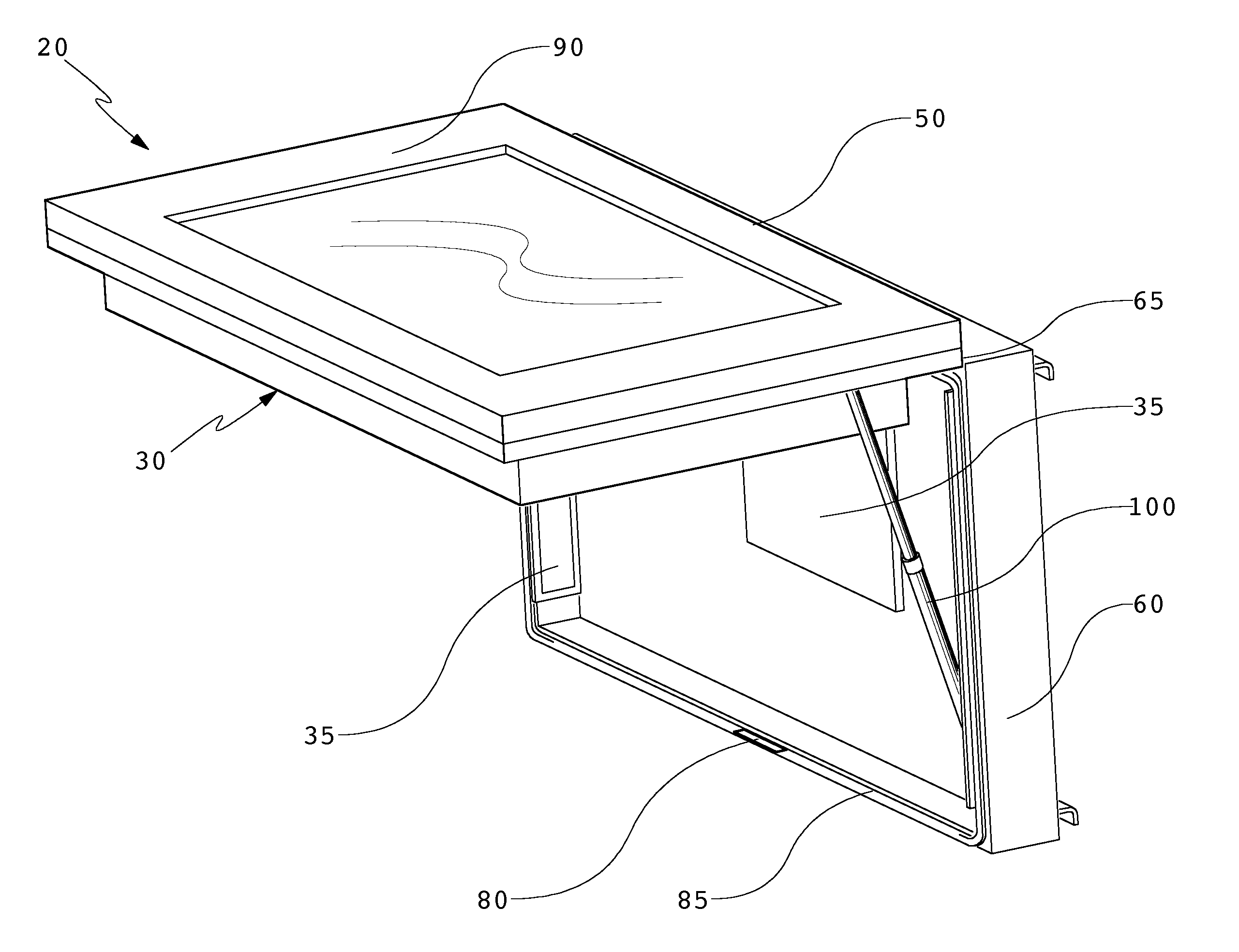
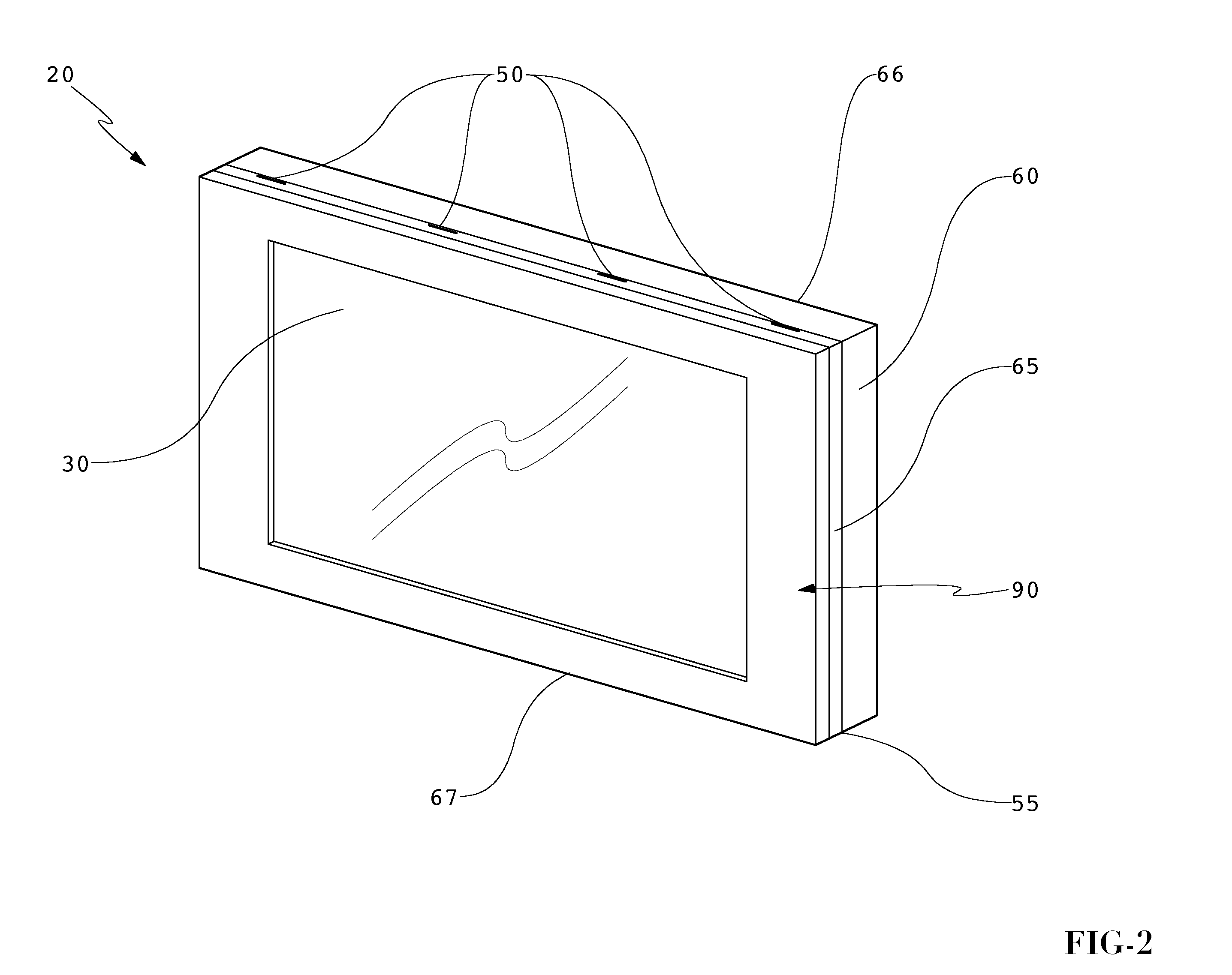
An electronic display which can be serviced without having to remove the display from its mounted position. A front housing and a rear housing are hingedly attached so that the front housing can rotate and allow access to the interior of the display. An axial force mechanism can be used to aid in rotating the front housing to an open position. A locking collar, support member, or axial locking member may be used to ensure that the front housing remains open. A removable front glass assembly or removable glass panel may be used with an exemplary embodiment. The front glass assembly or glass panel can be easily replaced if it becomes damaged by minimally-trained personnel. Gutters may be used between the front and rear housing as well as the front housing and front glass assembly to ensure an adequate seal against contaminates.

Description

CROSS-REFERENCE TO RELATED APPLICATIONS[0001]This application is a non-provisional application and does not claim priority to any co-pending applications.BACKGROUND OF THE INVENTIVE FIELD[0002]The exemplary embodiments herein are directed towards an electronic display which can be serviced or repaired while remaining in a mounted position.SUMMARY OF THE GENERAL INVENTIVE CONCEPT[0003]Electronic displays are now being used for not only indoor entertainment purposes, but are now being utilized for indoor and outdoor advertising / informational purposes. For example, liquid crystal displays (LCDs), plasma displays, light emitting diode (LED), electroluminescence, light-emitting polymers, organic light emitting diode displays (OLEDs) and many other flat panel displays can now be used to display information and advertising materials to consumers in locations outside of their own home or within airports, arenas, transit stations, stadiums, restaurants / bars, gas station pumps, billboards, an...

Claims


Application Information

Patent Timeline
IPC IPC(8): H05K7/20H05K7/00
CPCH04N5/64A47B81/06Y10T29/4973H05K5/06H05K5/0017H05K5/0204H05K5/0221H05K5/0226
Inventor DUNN, WILLIAMBEDELL, WARELE, DONWILLIAMS, DAVID
Owner MFG RESOURCES INT INC
Learn More