Windmill

a windmill and wind power technology, applied in wind energy generation, motors, dynamo-electric machines, etc., can solve the problems of reducing the service life of a gearbox between use, unable to make the generator ready for use prior to mounting, and design giving the air control not necessary, so as to reduce the effect of bending moment and simple structur

Inactive Publication Date: 2005-06-28
SCAN WIND GROUP
View PDF10 Cites 108 Cited by
  • Summary
  • Abstract
  • Description
  • Claims
  • Application Information

AI Technical Summary

Benefits of technology

[0005]It has also been proposed to arrange the generator on the opposite side of the wind turbine relative to the top of the tower and connect the wind turbine to the generator over a turbine shaft between the hub and the rotor of the generator—either in a rigid connection or over a coupling which transfers no bending moment, and without an intermediate gearbox—and wherein the turbine shaft and the generator are journalled in a support arrangement with two or more bearings integrated in the support arrangement. The purpose of this arrangement is to reduce the bending acting on the part of the shaft adjoining the generator, by forcing the shaft through radial reaction forces from the bearing, back to the neutral position relative to the bending of the shaft without this arrangment, to have a tight as possible air gap between the rotor and the stator. With this solution the bearings are subject to high bearing forces, and additionally the design requires a very rigid base to accomodate the increased bearing.OBJECT
[0006]The main object of the invention is to provide a wind power plant wherein the stator and the rotor during operation maintain their mutual distance (air gap), independent on the deflection of the turbine shaft due to the bending moment acting on the hub of the wind turbine in the cases where the turbine shaft is connected directly to the generator. In the embodiments wherein a gearbox is arranged between the turbine shaft and the generator, the invention should relieve the gearbox from unexpected forces, which may reduce the service life relative to the norm.THE INVENTION
[0009]This provides an advantageous combination of simple structure and favourable journalling properties which contributes to keep the air gap between the rotor and the stator of the generator as small and constant as possible during the operation of the wind power plant, and without straining the bearings excessively due to the forces created by the bending moment acting on the hub.

Problems solved by technology

A major technical challenge in the design and development of wind power plants, is to ensure that the bending moment acting on the turbine hub from the blades does not create damaging deformations in the remaining structure.
This relates particularly to deformations which may influence the air gap between the rotor and the stator when the turbine shaft carries an electric generator without any intermediate gearbox, or deformations straining the wheels of the gearbox and reducing the service life when a gearbox is used between the turbine shaft and the generator
Experience shows that this design does not give the necessary control of the air gap between the rotor and the stator upon a bending moment strain being set up on the turbine shaft from the hub of the wind turbine.
Also the generator can not be made ready for use prior to mounting.
Calculations shows that even this design will not provide a desirable constant air cap, when the wind turbine exceeds a certain size in power and weight, without making the dimensions of the supporting base unecessary large.
With this solution the bearings are subject to high bearing forces, and additionally the design requires a very rigid base to accomodate the increased bearing.

Method used


Image

  • Windmill
  • Windmill
  • Windmill

Examples


Embodiment Construction

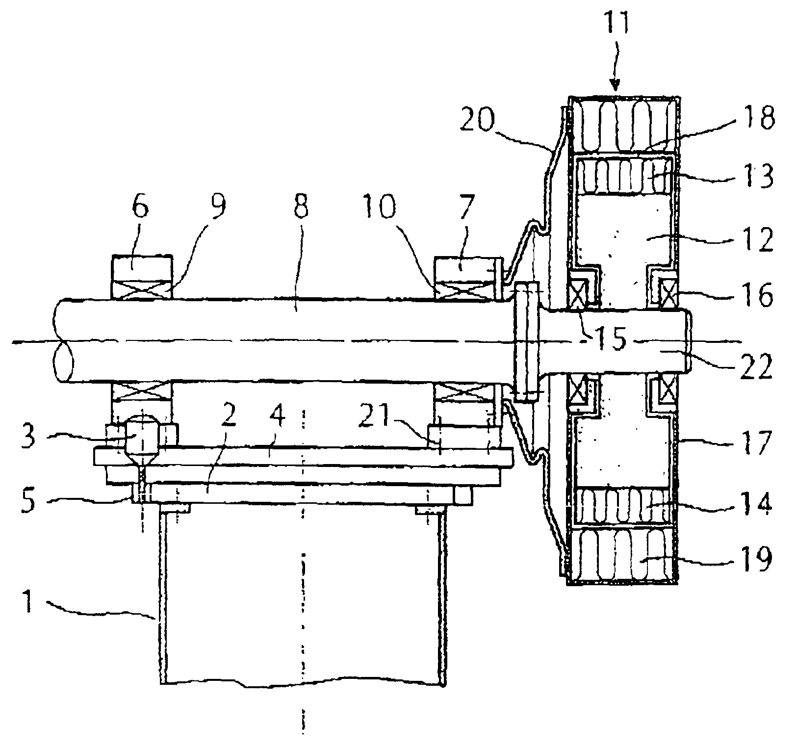
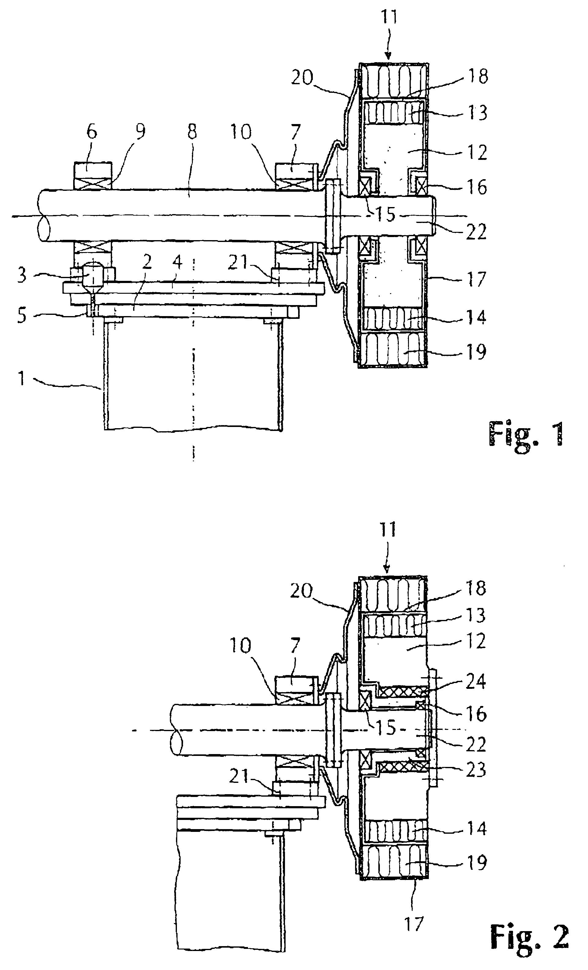
[0013]The invention is further described below with reference to the drawings wherein:

[0014]FIG. 1 shows a vertical section through an embodiment with a two-sided journalling of the stator on the shaft,

[0015]FIG. 2 shows a vertical section of a corresponding embodiment with a single-sided journalling of the stator on the shaft,

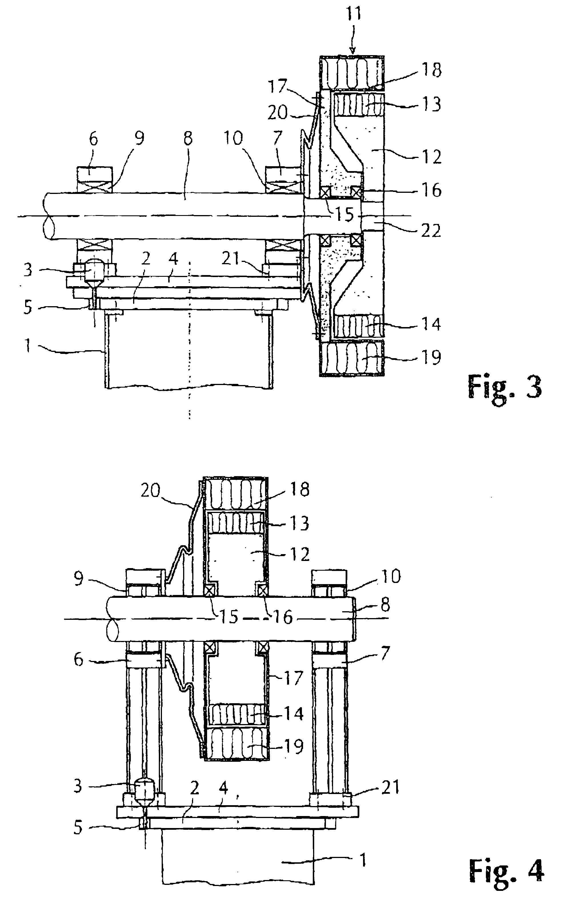
[0016]FIG. 3 shows a vertical section through a third embodiment with a two-sided journalling of the stator, which is carried by the shaft,

[0017]FIG. 4 shows a vertical section through a further embodiment of the invention, with the generator arranged between two bearings,

[0018]FIG. 5 shows a perspective view of an alternative embodiment of a non-rotatable coupling,

[0019]FIG. 6 shows a perspective view of an alternative embodiment, with a gearbox connected to the turbine shaft, with a generator further being arranged on a generator support carried by the gear box in the extension of the, and wherein the torque transmission to the main base is provided by an ad...


PUM


Abstract

Wind power plant with a wind turbine with a turbine shaft with which a generator shaft, which can be an extension of the turbine shaft, is connected to the rotor (12) of an electric generator. The rotor is radially surrounded by a stator, the turbine shaft is journalled in two bearing housings with bearings arranged on a base at the top of a tower, the base is pivotable around a vertical axis, and a motor is provided to effect the pivoting. The generator shaft is integrated with or rigidly connected to a flexing turbine shaft, the stator and rotor are carried by the generator shaft, to allow the generator to follow the flexing movement of the turbine shaft and the stator is locked against turning by a non-rotatable coupling which transfers substantially no bending moment or axial force acting against the flexing of the turbine shaft due to the bending moment acting on the turbine shaft from its hub, the bearings being provided to allow flexing of the turbine shaft.

Description

[0001]The invention relates to a wind power plant according to the introduction of claim 1.PRIOR ART AND ITS WEAKNESSES[0002]A major technical challenge in the design and development of wind power plants, is to ensure that the bending moment acting on the turbine hub from the blades does not create damaging deformations in the remaining structure. This relates particularly to deformations which may influence the air gap between the rotor and the stator when the turbine shaft carries an electric generator without any intermediate gearbox, or deformations straining the wheels of the gearbox and reducing the service life when a gearbox is used between the turbine shaft and the generator[0003]It is known to provide having wind turbine powering a generator arranged at the top of a column or tower. One solution is to connect the hub of the wind turbine directly to the rotor. The rotor is in turn carried by a base connected to the top of the tower, and the stator is carried by the base wit...

Claims


Application Information

Patent Timeline
Patent Type & Authority Patents(United States)
IPC IPC(8): F03D9/00F03D11/02F03D11/00
CPCF03D9/002F03D11/00H02K7/1838F03D11/02Y02E10/722Y02E10/725F03D80/00F03D15/00F03D9/25F03D15/10F03D80/70Y02E10/72Y02E70/30
Inventor PETTERSEN, TOROLFWICKSTROM, ANDERSLINDBERG, MIKAEL
Owner SCAN WIND GROUP
Why Eureka
Try Eureka