Camera bracket for annular lamp

A ring light and camera technology, applied in the direction of camera, machine/stand, camera body, etc., can solve the problems of inconvenient operation, inconvenient operation, unable to ensure that the camera and the ring light maintain the same optical axis, etc. The effect of convenient operation

Inactive Publication Date: 2012-05-30
FUZHOU BOLING PHOTOGRAPHIC EQUIP
View PDF6 Cites 1 Cited by
  • Summary
  • Abstract
  • Description
  • Claims
  • Application Information

AI Technical Summary

Problems solved by technology

[0003] The up and down adjustment and front and rear adjustment of the camera bracket of the prior art ring light are adjusted with 2 knobs respectively. Move the camera bracket up with only one hand. Since the left and right sides of the bracket are completely independent, it is very inconvenient to move at the same time, especially it is difficult to ensure the balance of the two sides and keep them at the same height.
In addition, for the same reason, when the camera wants to move back and forth, you must also loosen the two screws on the balance bracket, and then use two hands to move the bracket back and forth. Ring lights on the same optical axis
Mainly explain two points, one is that the original technology is inconvenient to operate, whether it is inconvenient to adjust up and down or back and forth
Second, it cannot guarantee that the camera and the ring light maintain the same optical axis

Method used


Image

  • Camera bracket for annular lamp
  • Camera bracket for annular lamp
  • Camera bracket for annular lamp

Examples


Embodiment Construction

[0023] In order to describe the technical content, structural features, achieved goals and effects of the present invention in detail, the following will be described in detail in conjunction with the embodiments and accompanying drawings.

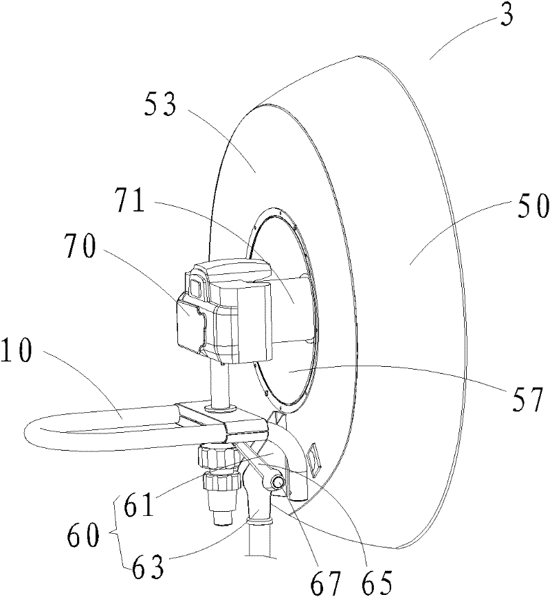
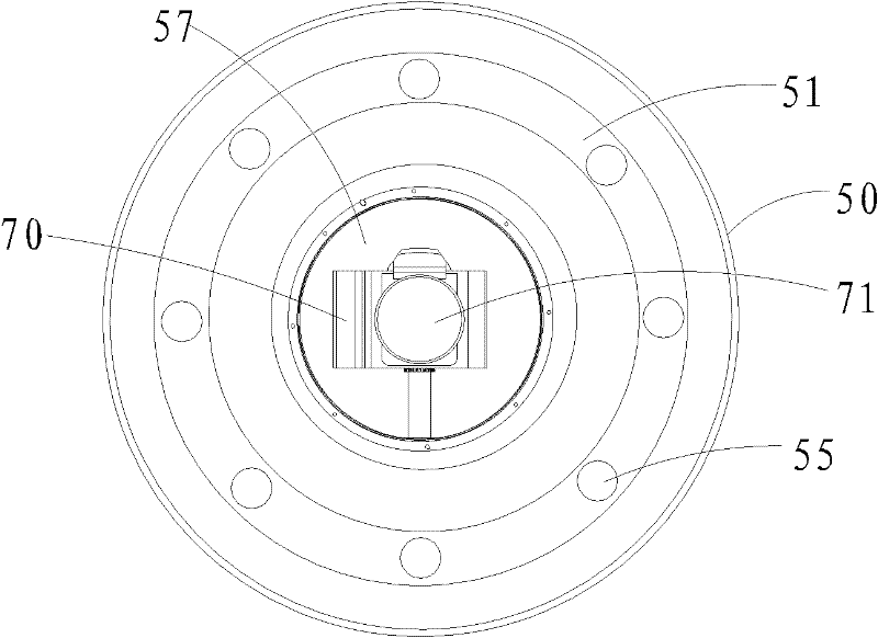
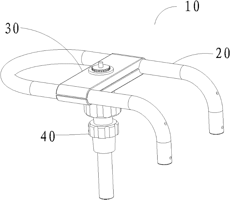
[0024] see figure 1 and figure 2 , the camera adjustment part 3 includes a support 60, a ring light 50 and a camera bracket 10 for the ring light, the ring light 50 is fixed on the support 60, and the camera bracket 10 for the ring light is fixed on the backlight of the ring light 50 Face 53.

[0025] The supporting member 60 includes a support rod 63 and a rotating member 61, the rotating member 61 is fixed on the backlight surface 53 of the ring light 50, the supporting rod 63 and the rotating member 61 are rotatably connected through a threaded rotating shaft 67, on the rotating shaft 67 is provided with a rotating wrench 65 for adjusting the angle of the rotating part 61. During use, only the rotating wrench 65 needs to be turned. ...


PUM


Abstract

The invention discloses a camera bracket for an annular lamp, which comprises a track support, a sliding unit and a lifting unit. The sliding unit is slidably arranged on the track support, the location of the sliding unit on the track support is adjusted by a sliding adjusting unit, the lifting unit is assembled on the sliding unit, and a lifting adjusting unit adjusts the location of the lifting unit in the vertical direction. The camera bracket for the annular lamp can conveniently adjust the locations of a camera in the horizontal direction and the vertical direction, adjustment precisionis guaranteed via a bracket structure, the problem of errors due to manual adjustment is avoided, manual adjustment experience insufficiency also cannot affect the adjustment precision, and accordingly the camera bracket brings convenience for operators.

Description

technical field [0001] The invention relates to the field of camera equipment, in particular to a camera bracket for a ring light. Background technique [0002] When shooting, lighting equipment is a photographic equipment used to increase the brightness of the subject and improve the image effect. When using lighting equipment for shooting, in order to achieve shadow-free shooting, you can use the ring light to cover the camera lens for shooting. [0003] The up and down adjustment and front and rear adjustment of the camera bracket of the prior art ring light are adjusted with 2 knobs respectively. Move the camera bracket upwards with only one hand. Since the left and right sides of the bracket are completely independent, it is very inconvenient to move at the same time, especially it is difficult to ensure the balance of the two sides and keep them at the same height. In addition, for the same reason, when the camera wants to move back and forth, you must also loosen the...

Claims


Application Information

Patent Timeline
Patent Type & Authority Applications(China)
IPC IPC(8): G03B17/56F16M11/04F16M11/24
Inventor 詹小洪詹蔚
Owner FUZHOU BOLING PHOTOGRAPHIC EQUIP
Why Eureka
Try Eureka