
Optical touch control system and sensing method thereof

An optical touch and sensor technology, used in instruments, electrical digital data processing, input/output process of data processing, etc. standard and other problems, to achieve the effect of simple calculation method

Inactive Publication Date: 2014-12-10
PIXART IMAGING INC
View PDF6 Cites 0 Cited by
  • Summary
  • Abstract
  • Description
  • Claims
  • Application Information

AI Technical Summary

Problems solved by technology

[0004] However, on the basis of the single-touch (Single Touch) technology, the multi-touch technology developed should be able to accurately determine the coordinates of multiple touch points on the touch screen at the same time. many difficulties
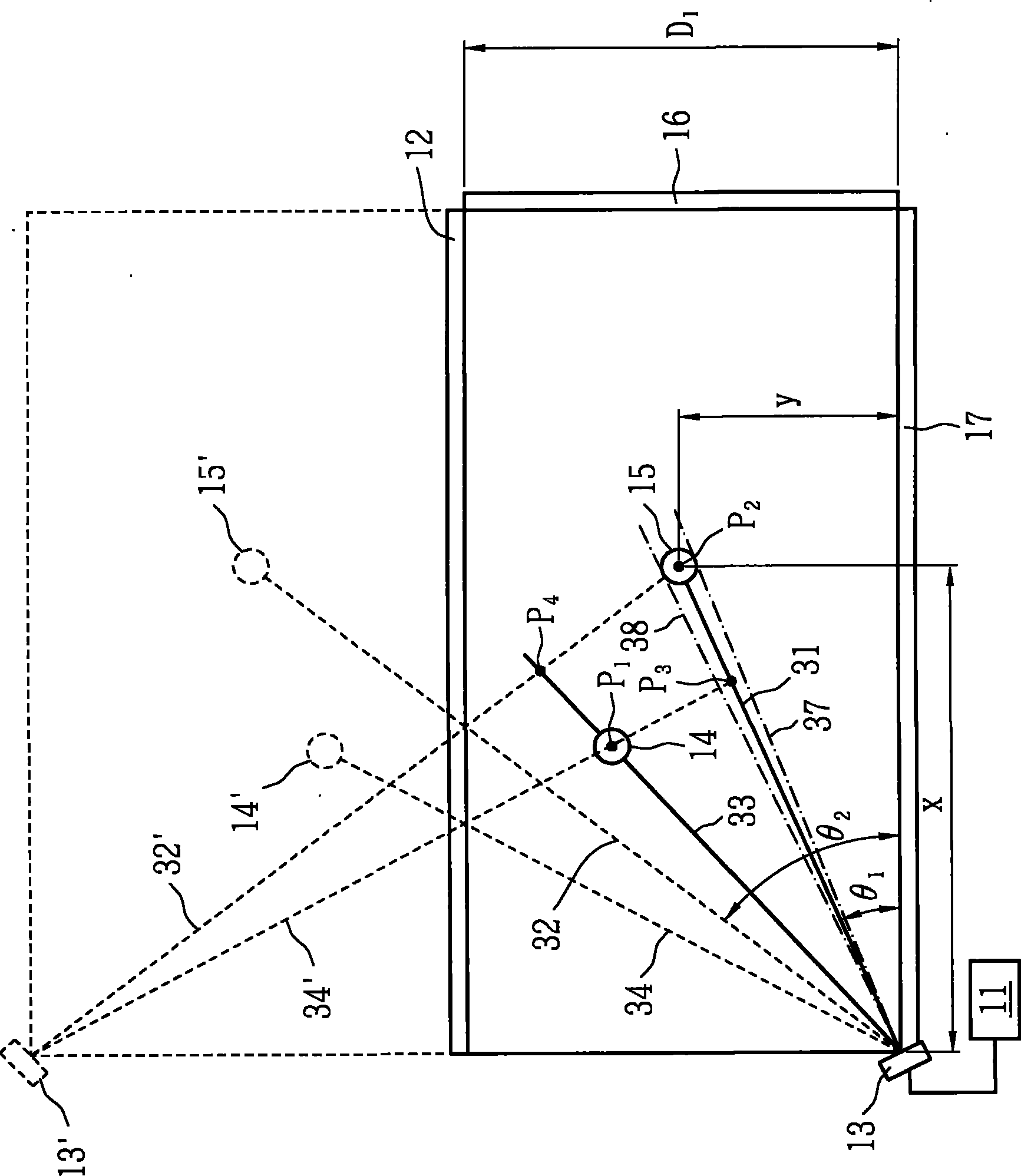
For example, in the case of an optical touch screen device, when two fingertips touch the touch screen, the controller will calculate four coordinates based on the extracted sensing image, but cannot directly calculate the real position of the two fingertips. Therefore, it is still difficult for existing optical touch screen devices to easily calculate the coordinates of multi-touch points

Method used


Image

  • Optical touch control system and sensing method thereof
  • Optical touch control system and sensing method thereof
  • Optical touch control system and sensing method thereof

Examples


Embodiment Construction

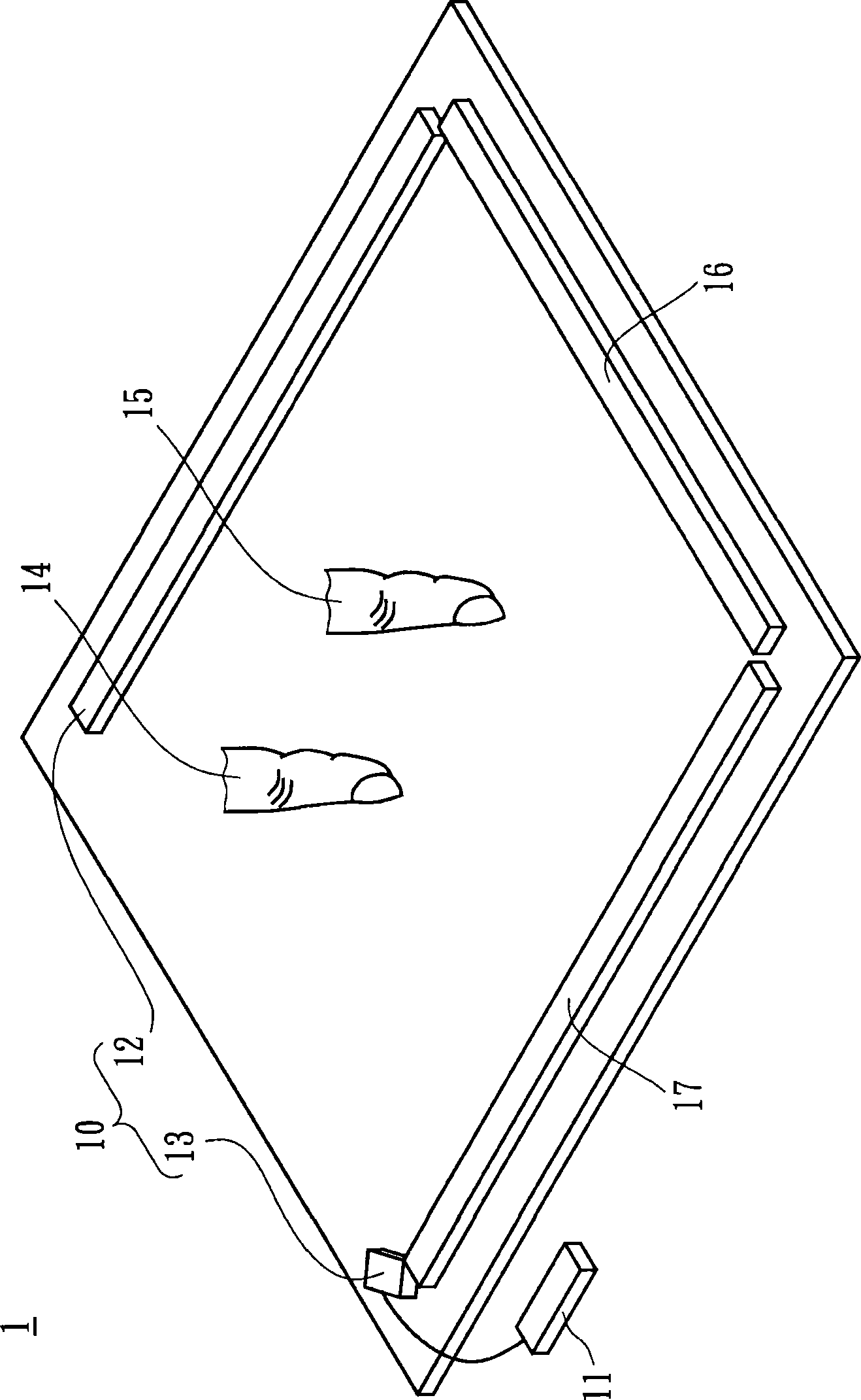
[0056] figure 1It is a schematic diagram of an optical touch system 1 according to an embodiment of the present invention. The optical touch system 1 is a multi-touch system, which can select the correct coordinates from the calculated coordinates of the objects 14 and 15 by using the optical characteristics of the objects 14 and 15 in the image. The optical touch system 1 includes a sensing unit 10 and a processing unit 11 , wherein the processing unit 11 is coupled to the sensing unit 10 . The sensing unit 10 is used to provide images of the coordinates of the objects 14 and 15 for analysis, and the processing unit 11 calculates the coordinates of the objects 14 and 15 according to the images provided by the sensing unit 10 .

[0057] In one embodiment, the sensing unit 10 includes a mirror element 12 and a sensor 13 . The mirror element 12 can surround a sensing area together with two strip elements 16 and 17 , wherein the strip elements 16 and 17 can be light emitting el...


PUM


Abstract

The invention discloses an optical touch control system and a sensing method thereof. The optical touch control system comprises a sensing unit and a processing unit, wherein the sensing unit comprises a first sensor and a second sensor. An image is extracted by each one of the first sensor and the second sensor, wherein each image comprises image information of a plurality of objects. The processing unit generates a group of standby coordinates according to the image information of the objects in the image, and selecting a part of the coordinates from the group of the standby coordinates to output as output coordinates according to optical features of the image information of the objects in the image. The optical touch control system provided by the invention can select real coordinates of the objects from the standby coordinates. Meanwhile, a coordinate calculating method provided by the invention is simple, so that the coordinates of a plurality of touch-control points can be rapidly and effectively calculated.

Description

technical field [0001] The present invention relates to a touch control system, in particular to a touch control system capable of judging correct object coordinates by using optical features such as image information or image information. Background technique [0002] A touch screen device, a popular input method for computer systems, allows users to directly perform input operations on the screen. The user can use a stylus, fingertip or the like to touch the screen. After the touch screen device detects and calculates the position of the touch, the coordinates are output to the computer system for subsequent calculation and processing. So far, many touch technologies have been developed to detect the touch position, including: resistive, capacitive, infrared, surface acoustic wave, magnetic , electrostatic (near field imaging) and other technologies. [0003] Single-touch (Single Touch) technology, which detects a touch event generated by a single finger or a stylus and...

Claims


Application Information

Patent Timeline
Patent Type & Authority Patents(China)
IPC IPC(8): G06F3/042
Inventor 苏宗敏蔡政男林志新彭元昱林育佳许登伟吕俊毅
Owner PIXART IMAGING INC
Learn More