
Manufacturing method for shallow trench isolation structure

A technology of isolation structure and manufacturing method, applied in semiconductor/solid-state device manufacturing, electrical components, circuits, etc., can solve the problems of poor reliability of component leakage current components, inappropriateness, incomplete groove filling, etc., to avoid components The effect of leakage current and good isolation capability

Inactive Publication Date: 2012-05-30
MACRONIX INT CO LTD
View PDF4 Cites 0 Cited by
  • Summary
  • Abstract
  • Description
  • Claims
  • Application Information

AI Technical Summary

Problems solved by technology

When the shallow trench isolation structure shrinks with the improvement of integrated circuit integration, the accompanying problem is the incomplete filling of the oxide layer in the trench due to the high aspect ratio of the trench. The problem, so that there will be holes in the final formed shallow trench isolation structure
If there are holes in the shallow trench isolation structure, the isolation capability of the shallow trench isolation structure will be deteriorated, which will cause problems such as component leakage current or component reliability deterioration.
[0006] It can be seen that the above-mentioned existing shallow trench isolation technology obviously still has inconvenience and defects in terms of method and use, and needs to be further improved urgently.
In order to solve the above-mentioned problems, the relevant manufacturers have tried their best to find a solution, but no suitable design has been developed for a long time, and the general method has no suitable method to solve the above-mentioned problems. This is obviously related. The problem that the industry is eager to solve

Method used


Image

  • Manufacturing method for shallow trench isolation structure
  • Manufacturing method for shallow trench isolation structure
  • Manufacturing method for shallow trench isolation structure

Examples


Embodiment Construction

[0066] In order to further explain the technical means and effects of the present invention to achieve the intended purpose of the invention, the specific implementation of the shallow trench isolation structure manufacturing method and ditch filling method according to the present invention will be described below in conjunction with the accompanying drawings and preferred embodiments. , method, step, feature and effect thereof, detailed description is as follows.

[0067] The aforementioned and other technical contents, features and effects of the present invention will be clearly presented in the following detailed description of preferred embodiments with reference to the drawings. Through the description of the specific implementation mode, a more in-depth and specific understanding of the technical means and effects adopted by the present invention to achieve the intended purpose can be obtained. However, the accompanying drawings are only for reference and description, a...


PUM


Abstract

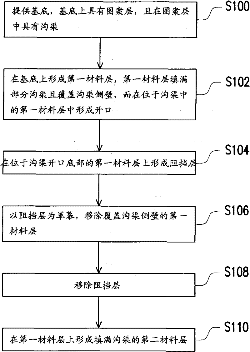
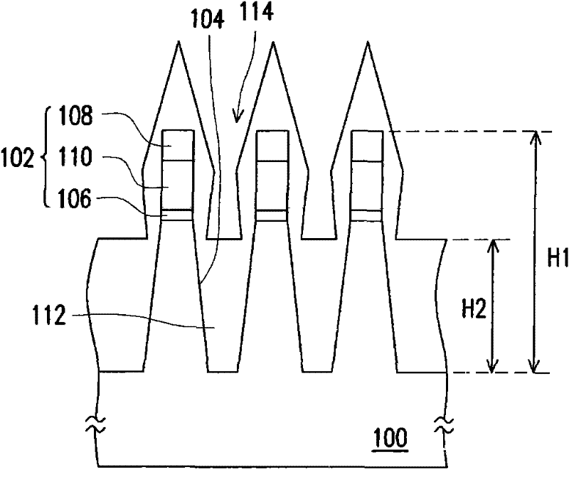
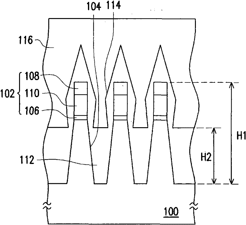
The invention relates to a manufacturing method for a shallow trench isolation structure and a trench filling method for same. The manufacturing method for the shallow trench isolation structure includes the steps: firstly, providing a substrate with a mask layer and forming trenches in the substrate and the mask layer; secondly, forming first dielectric layers on the substrate and filling parts of the trenches and covering the side walls of the trenches with the first dielectric layers to form openings in the first dielectric layers positioned in the trenches; thirdly, forming barrier layers on the first dielectric layers positioned at the bottoms of the openings; fourthly, removing the first dielectric layers covering the side walls of the trenches by using the barrier layers as masks; fifthly, removing the barrier layers; and sixthly, forming second dielectric layers for filling the trenches.

Description

technical field [0001] The invention relates to a method for manufacturing a semiconductor component, in particular to a method for manufacturing a shallow trench isolation structure and a ditch filling method. Background technique [0002] With the advancement of semiconductor technology, the size of components is also continuously reduced. In order to prevent short circuits between adjacent components, the isolation between components has become very important. [0003] A more common isolation technology between elements is local oxidation of silicon (LOCOS). However, the partial silicon oxidation method has several disadvantages, including problems related to stress and bird's beak formed around the isolation structure. Therefore, a replacement method is a shallow trench isolation (shallow trench isolation, STI) structure process. [0004] The traditional shallow trench isolation structure is formed by first forming a trench in the semiconductor substrate by using aniso...

Claims


Application Information

Patent Timeline
IPC IPC(8): H01L21/762H01L21/311
Inventor 骆统杨镇豪苏金达杨令武杨大弘陈光钊
Owner MACRONIX INT CO LTD
Learn More