Motor vehicle lock

A technology of latching and rotating latches, which can be used in vehicle locks, building locks, lock applications, etc., and can solve problems such as small stability and reduced mechanical stability.

Active Publication Date: 2012-05-30
KIEKERT AG
View PDF4 Cites 4 Cited by
  • Summary
  • Abstract
  • Description
  • Claims
  • Application Information

AI Technical Summary

Problems solved by technology

But with such measures the mechanical stability of the shaft is reduced
Possibilities related to this are limited because minimum stability must be maintained

Method used


Image

  • Motor vehicle lock
  • Motor vehicle lock

Examples


Embodiment Construction

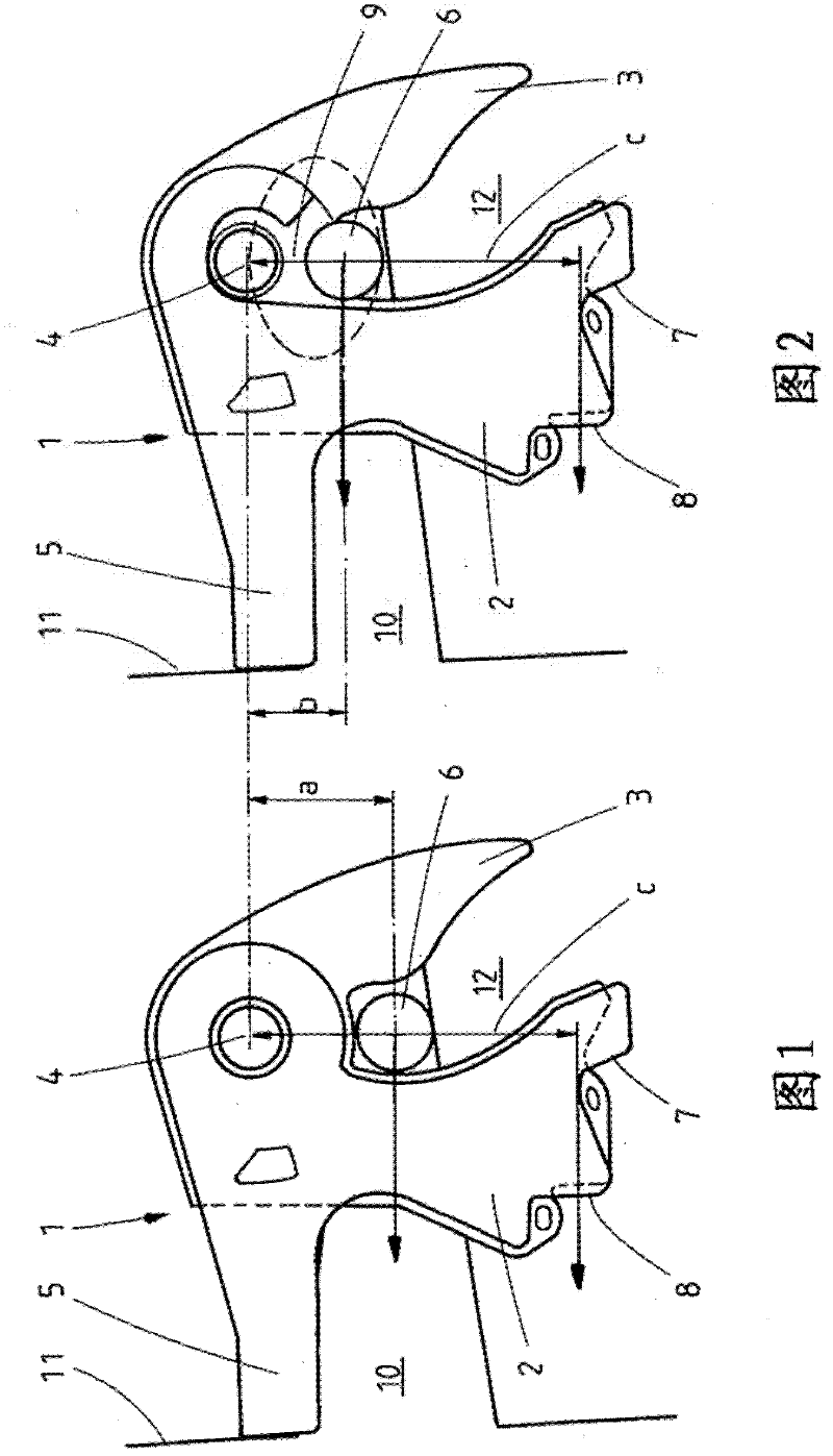
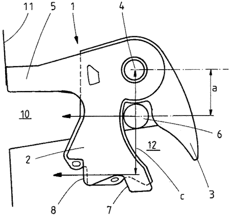
[0029] figure 1 with 2 The top view showing the locking mechanism in the main locking position, it has a rotary latch 1, the rotary latch includes a load arm 2 and a catch arm 3, and the rotary latch is rotatably supported by the rotary latch shaft 4. The load arm 2 prevents the lock pin 6 from leaving the entrance slot 10 of the lock box. The locking pawl required for locking in the main locking portion 8 is not shown for the sake of clarity.

[0030] As compared figure 1 with 2 As clearly seen, in the embodiment according to the present invention ( figure 2 ) Chinese and traditional structure ( figure 1 Compared with ), the distance between the rotary latch shaft 4 and the lock pin 6 is significantly reduced. And in accordance with figure 1 The traditional embodiment shown is different, in figure 2 In the embodiment according to the invention shown in there is a relatively narrow tab 9 made of plastic, which separates the rotary latch shaft 4 from the lock pin 6 in the main...


PUM


Abstract

The invention relates to a lock comprising a locking mechanism having a rotary latch which consists at least to some extent of metal and which contains a load arm and a detent arm, the rotary latch being rotationally mounted on a rotary latch shaft and being adapted to accommodate a lock holding pin, the metal part of said load arm not entirely extending around the rotary latch shaft and being preferably open towards the lock holding pin in the main position of detent. Preferably, the load arm is designed in such a manner as to support itself on the lock wall when in the main detent position. The invention further relates to the use of a lock according to the invention in a motor vehicle.

Description

Technical field [0001] The invention relates to a lock for a motor vehicle having the features of the preamble of claim 1. The invention also relates to the use of the lock according to the invention in a motor vehicle. Background technique [0002] The lock mentioned at the beginning includes at least one lock housing, which has a lock plate (also called a lock box) usually made of metal arranged in the lock housing, and has a lock plate supported on the lock plate. Locking mechanism. The lock plate is usually provided with an inlet seam for receiving the lock pin. The locking mechanism includes a rotary latch that is rotatably supported for accommodating the lock pin. The locking mechanism also has a locking pawl, and the rotating lock bolt can be locked by the locking pawl. [0003] The rotary latch of a motor vehicle lock generally has a fork-shaped inlet seam formed by a load arm and a catch arm. The lock pin of a motor vehicle door or cover (such as an engine cover or a t...

Claims


Application Information

Patent Timeline
Patent Type & Authority Applications(China)
IPC IPC(8): E05B17/00E05B65/12E05B65/32
CPCE05B17/0045E05B77/02E05B85/26E05B77/36
Inventor H・席费尔
Owner KIEKERT AG
Why Eureka
Try Eureka