Automatic shoe depositing and taking device
An automatic access and shoe board technology, applied in wardrobes, home appliances, furniture parts, etc., can solve problems that cannot meet the needs of high-quality life, and achieve the effect of convenience
Inactive Publication Date: 2013-07-31
NINGBO UNIV
View PDF5 Cites 0 Cited by
- Summary
- Abstract
- Description
- Claims
- Application Information
AI Technical Summary
Problems solved by technology
At present, the shoe cabinets used in the homes of residents in our country basically adopt a cabinet structure. When people go out or go home, they need to go through five procedures of opening the door, taking shoes, changing shoes, putting shoes, and closing the door to change a pair of shoes. It brings a lot of inconvenience to people when changing shoes, and it is far from meeting people's needs for high-quality life.
Method used
View moreImage
Smart ImageViewing Examples
Examples
Embodiment Construction
Login to View More PUM
 Abstract
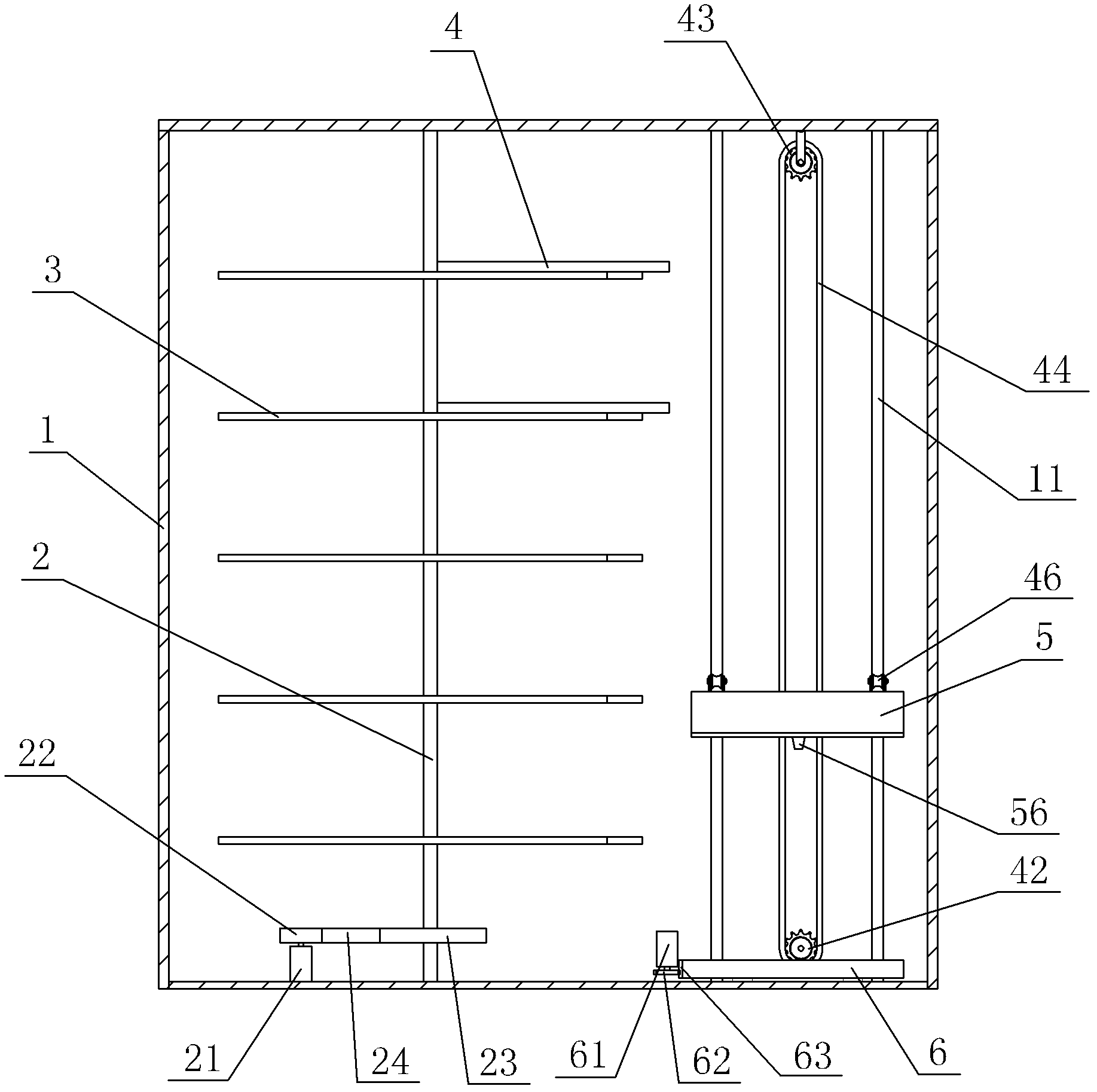
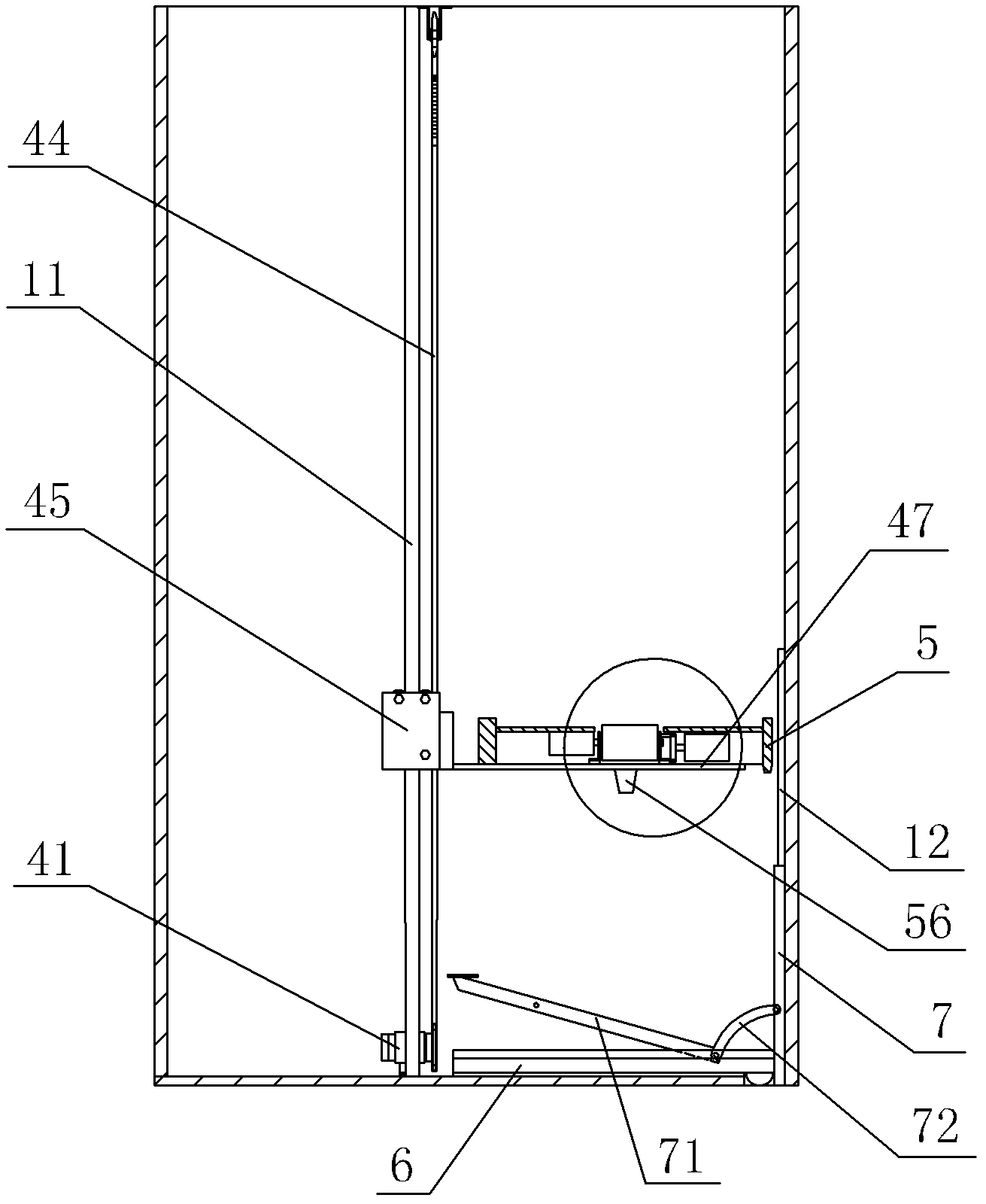
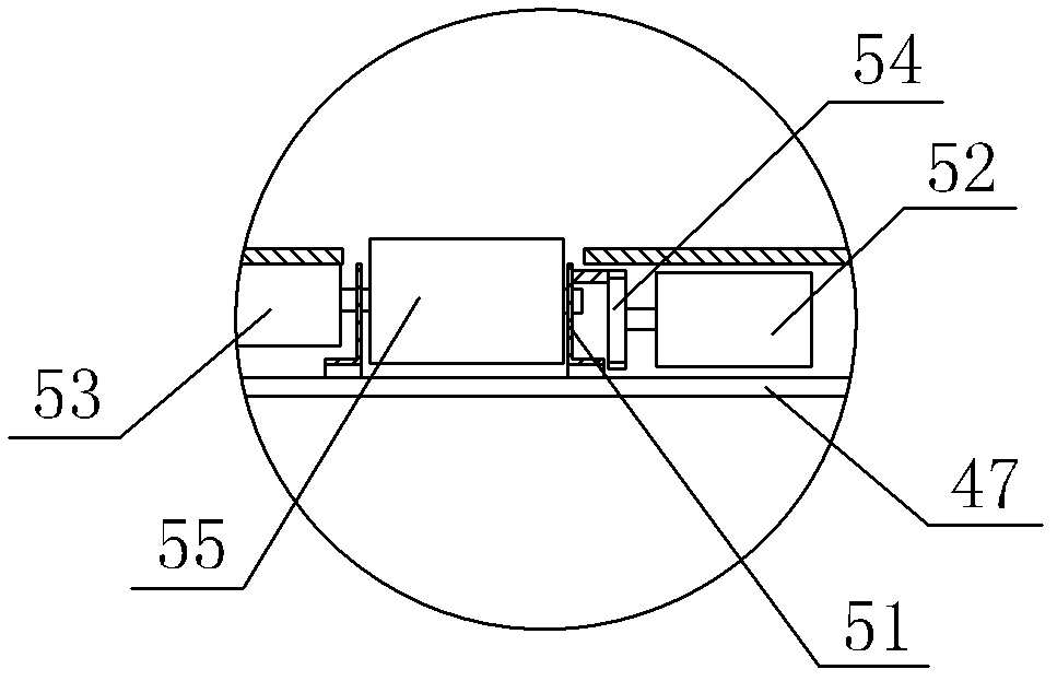
The invention discloses an automatic shoe depositing and taking device which comprises a cabinet body; a rotating shaft and a rotating shaft driving mechanism are arranged in the cabinet body; a plurality of layers of brackets arranged up and down are fixed on the rotating shaft; the shoe depositing and taking device is characterized in that a plurality of shoe holding plates are arranged on the brackets; a shoe holding plate delivery mechanism is arranged in the cabinet body and is positioned beside the brackets; a bottom plate is arranged at the bottom of the cabinet body; a bottom plate driving mechanism and a control system are arranged in the cabinet body; and the shoe holding plate delivery mechanism, the bottom plate driving mechanism and the rotating shaft driving mechanism are electrically connected with the control system respectively. The automatic shoe depositing and taking device has the advantage that the shoe holding plate delivery mechanism and the bottom plate drivingmechanism are arranged in the cabinet body, the shoe holding plates that hold shoes can be moved to a delivery platform from the brackets automatically by the shoe holding plate delivery mechanism, then the delivery platform is moved down to the bottom plate, and the shoe holding plates are moved out of the cabinet body through the bottom plate driving mechanism, so that shoes can be deposited and taken automatically, the use is very convenient, and the requirement of people for high-quality living can be met.
Description
technical field [0001] The invention relates to a storage device for shoes, in particular to an automatic shoe storage device. Background technique At present, the shoe cabinets used in the homes of residents in our country basically adopt a cabinet structure. When people go out or go home, they need to go through five procedures of opening the door, taking shoes, changing shoes, putting shoes, and closing the door to change a pair of shoes. Bring a lot of inconvenience when changing shoes to people, also can't satisfy people's demand to high-quality life far away. Contents of the invention The technical problem to be solved by the present invention is to provide an automatic shoe storage device that can automatically take and store shoes. The technical solution adopted by the present invention to solve the above-mentioned technical problems is: an automatic access shoe device, including a cabinet, the cabinet is provided with a rotating shaft and a rotating shaft dri...
Claims
Login to View More Application Information
Patent Timeline
 Patent Type & Authority Patents(China)
IPC IPC(8): A47B61/04A47B96/00A47B96/02
Inventor 李国富余建成赵均总何明腾李洪滨
Owner NINGBO UNIV
Features
- R&D
- Intellectual Property
- Life Sciences
- Materials
- Tech Scout
- Unparalleled Data Quality
- Higher Quality Content
- 60% Fewer Hallucinations
Learn More Browse by: Latest US Patents, China's latest patents, Technical Efficacy Thesaurus, Application Domain, Technology Topic, Popular Technical Reports.
© 2025 PatSnap. All rights reserved.Legal|Privacy policy|Modern Slavery Act Transparency Statement|Sitemap|About US| Contact US: help@patsnap.com


