Synchronous structure for twin countershaft transmission

A technology of double intermediate shafts and transmissions, applied in clutches, mechanical drive clutches, mechanical equipment, etc., can solve the problems affecting the service life and wear of the synchronizer, and achieve the effect of easy shifting, long service life and reducing shifting force.

Inactive Publication Date: 2012-06-13
SINO TRUK JINAN POWER
View PDF6 Cites 6 Cited by
  • Summary
  • Abstract
  • Description
  • Claims
  • Application Information

AI Technical Summary

Problems solved by technology

In neutral gear, since the synchronizer cone ring and the sliding disc are floatingly connected in the radial direction of the main shaft, the synchronizer cone ring will be eccentric with the gear gear under the action of gra

Method used


Image

  • Synchronous structure for twin countershaft transmission
  • Synchronous structure for twin countershaft transmission
  • Synchronous structure for twin countershaft transmission

Examples


Embodiment Construction

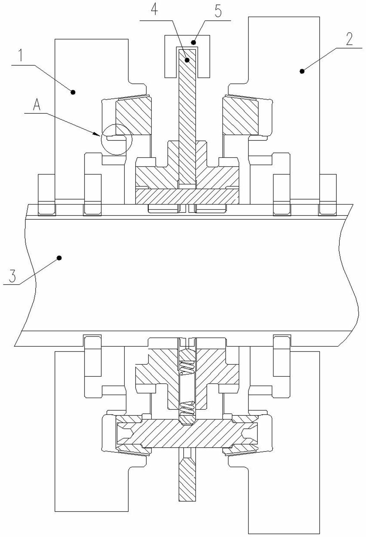
[0026] Such as figure 1 A specific embodiment is shown, which includes a main shaft 3, a synchronizer 4 arranged on the main shaft 3, and two gears I1 and II2.

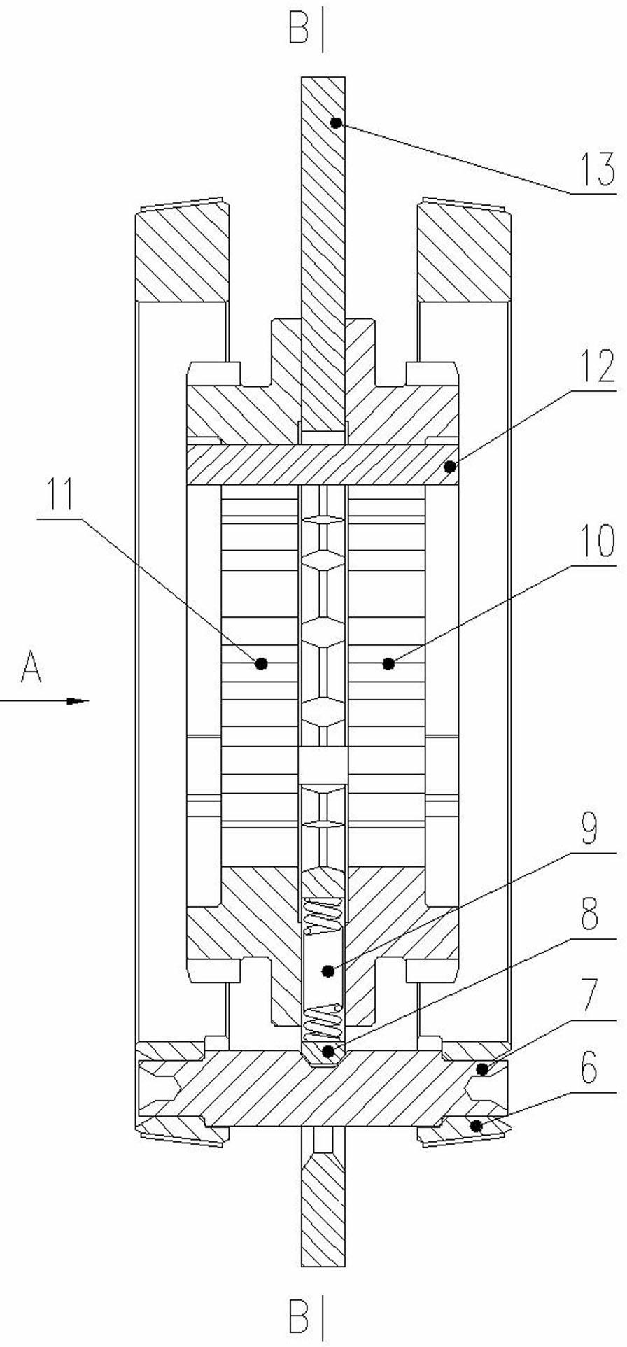
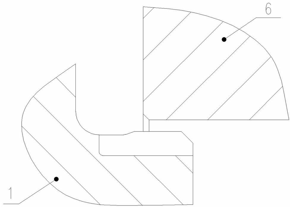
[0027] Such as figure 2 , Figure 5 with Image 6 As shown, the synchronizer includes a synchronizer cone ring 6, a locking pin 7, a positioning pin 8, a spring 9, a right sliding sleeve 10, a left sliding sleeve 11, a connecting plate 12 and a sliding disc 13, and there are two synchronizer cone rings 6. The two synchronizer cone rings 6, the right sliding sleeve 10, the left sliding sleeve 11 and the sliding disc 13 are all set on the main shaft 3, the left sliding sleeve 11 is located on the left side of the sliding disc 13, and the right sliding sleeve 10 is located on the right side of the sliding disc 13. side, such as Figure 4 The connecting plate 12 shown connects and fixes the right sliding sleeve 10, the left sliding sleeve 11 and the sliding disc 13 in the axial direction, and there is a certain amoun...


PUM


Abstract

The invention discloses a synchronous structure for a twin countershaft transmission. The synchronous structure comprises a main shaft, a synchronizer and two tap-position gears, wherein the synchronizer is arranged on the main shaft; each of two tap-position gears is provided with one boss extending into the inner circle of a corresponding synchronizer taper ring; at a neutral position, the inner circle surfaces of the synchronizer taper rings contact the bosses; and when a synchronous taper surfaces on the synchronizer taper rings contact the synchronous taper surfaces on the tap-position gears, the inner circle surfaces of the synchronizer taper rings do not contact the bosses on the tap-position gears. According to the synchronous structure for a twin countershaft transmission, the eccentricity of the synchronizer taper rings and the tap-position gears is controlled; at the neutral position, the synchronous taper surfaces of the synchronizer taper rings do not contact the synchronous taper surfaces of the tap-position gears; therefore, taper surfaces cannot be worn at the neutral position; and the service life is long. Because of the special connection structure of a sliding disk and the main shaft, self energizing effort can be generated, the shifting force is lowered, and the synchronous structure can conveniently shift.

Description

[0001] technical field [0002] The invention relates to a transmission for a double countershaft structure, in particular to a synchronous structure of a double countershaft transmission. Background technique [0003] The transmission with double countershaft structure has the advantages of compact structure, large transmission torque and long service life, and is widely used in medium and heavy trucks. Most of the transmissions with double countershaft structure use sliding sleeve shifting, which makes shifting difficult and requires higher requirements on the driver. The current production of dual countershaft transmissions with synchronizers, whether they are pin-type synchronizers or lock-ring-type synchronizers, has a relatively unsatisfactory lifespan of the synchronizers. [0004] The lock-pin synchronous structure of the existing double countershaft transmission includes a main shaft, a synchronizer arranged on the main shaft and two gear gears. The synchronizer in...

Claims


Application Information

Patent Timeline
IPC IPC(8): F16D23/04
Inventor 任福臣李发有石红云王颖颖陶磊
Owner SINO TRUK JINAN POWER
Why Eureka
Try Eureka