Air passage system of respirator

A technology of air circuit and ventilator, applied in the direction of respirator, etc., can solve the problems of difficult online calibration, inaccurate detection of the second flow sensor, insufficient detection accuracy, etc., so as to prolong the service time and life, and achieve the detection accuracy and reliability. , the effect of high detection accuracy

Inactive Publication Date: 2012-06-20
于邦仲
View PDF8 Cites 20 Cited by
  • Summary
  • Abstract
  • Description
  • Claims
  • Application Information

AI Technical Summary

Problems solved by technology

Since the flow detection system is integrated with the entire ventilator air circuit, it is difficult to perform routine online calibration
Although it can also be calibrated, it will inevitably affect the normal use of the ventilator or the accuracy of flow detection
On the other hand, the external detection is close to the user. Due to the uneven temperature and heat, the internal condensation of the second flow sensor probe FQ2, especially the detection of condensation water in the branch airway, causes the second flow sensor to detect inaccurately and the detection accuracy is not enough, thus affecting Precise control of the ventilator, and these technologies have not yet appeared in the ventilator or related technologies have not been disclosed

Method used


Image

  • Air passage system of respirator
  • Air passage system of respirator
  • Air passage system of respirator

Examples


Embodiment Construction

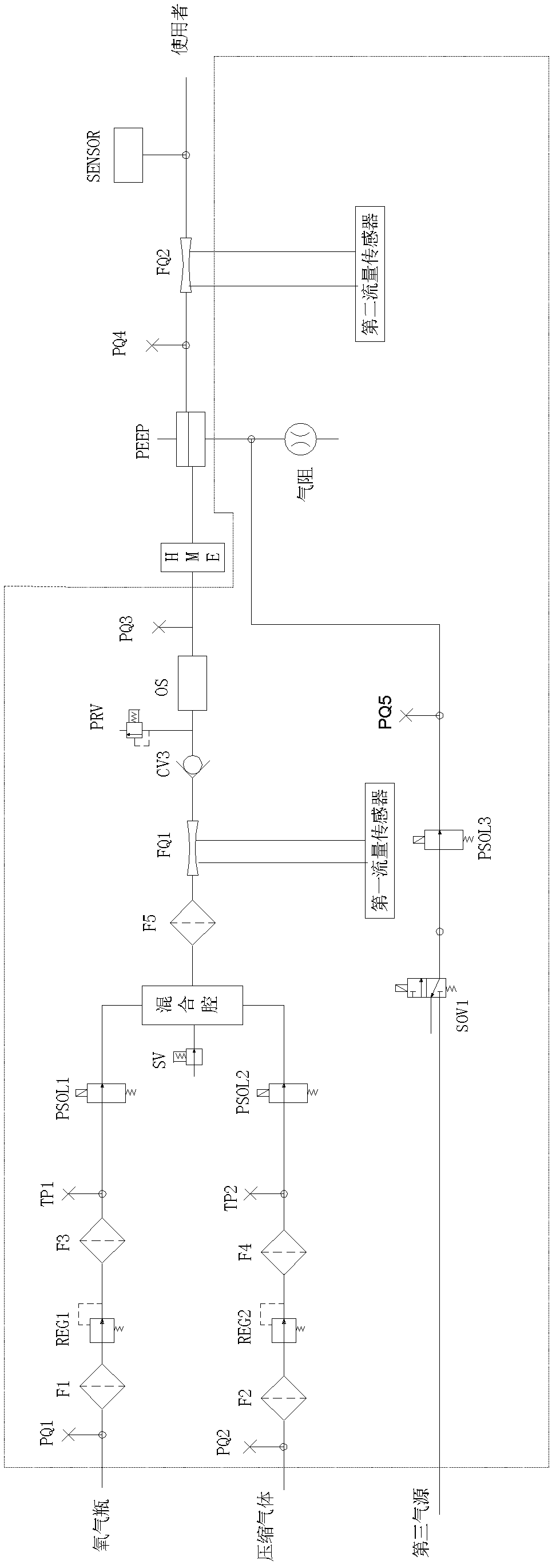
[0041] First, the air circuit system of the ventilator according to the specific embodiment of the present invention is described:

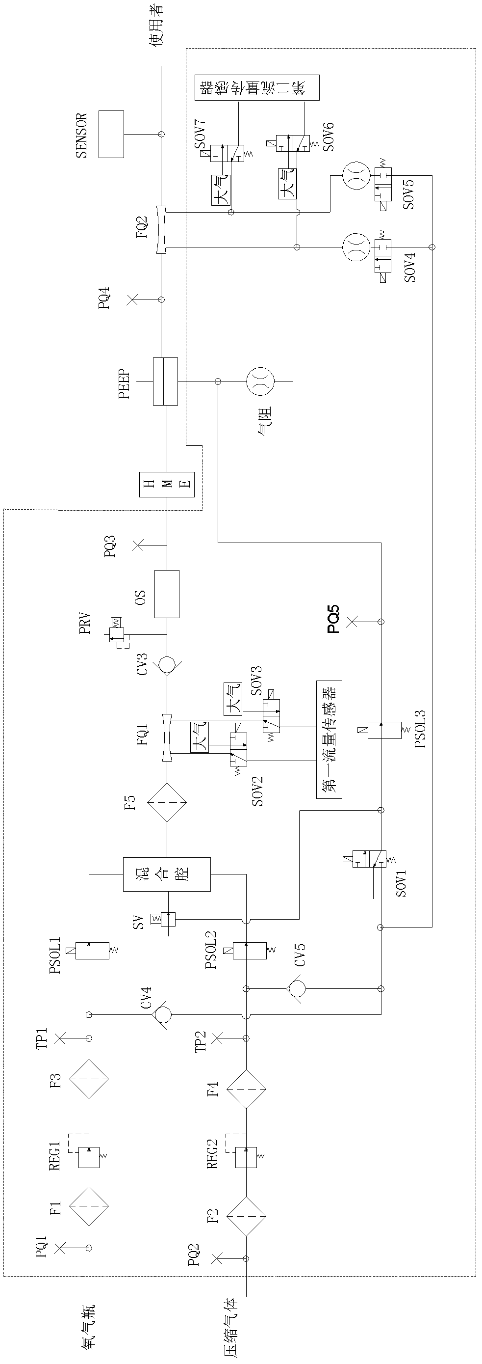
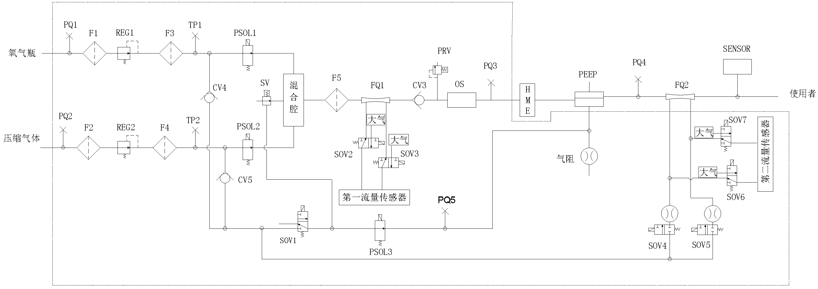
[0042] The gas system, the structure is as follows figure 2 As shown, on the basis of the air circuit system of the traditional ventilator, automatic calibration, automatic water removal, automatic gas selection and anti-suffocation free inhalation are added. in:

[0043] (1) Automatic calibration part

[0044] Including four newly added two-position three-way solenoid valves SOV2, SOV3, SOV6 and SOV7 of the present invention, they respectively select and connect the first flow sensor and the second flow sensor to the first flow sensor probe FQ1 and the second flow sensor through the corresponding air path. The flow sensor probe FQ2, or communicate with the external atmosphere that the present invention increases communication. When the first flow sensor communicates with the first flow sensor probe FQ1 and the second flow sensor communicates...


PUM


Abstract

The invention relates to an air passage system of a respirator. The air passage system comprises an oxygen communicating pipeline, as well as a pressure reducing valve (REG1) and a proportional valve (PSOL1), which are communicated on the oxygen communicating pipeline in series; a high-pressure air communicating pipeline, as well as the pressure reducing valve (REG2) and the proportional valve (PSOL2), which are communicated on the high-pressure air communicating pipeline in series; a mixing cavity and a free respiration valve (SV) communicated with the mixing cavity; a main pipeline, as well as a flow sensor probe (FQ1) and a one-way valve (CV3), which are communicated on the main pipeline in series; and a control air source, wherein the input end of the control air source is communicated with the oxygen communicating pipeline through an air passage beside a one-way valve (CV4), the air passage beside a one-way valve (CV5) is communicated with the high-pressure air communicating pipeline, and the output end of the control air source is communicated with the air inlet end of a two-position three-way valve (SOV1); the air outlet end of the SOV1 is communicated with the control end of the free respiration valve (SV) and a proportional valve (PSOL3), and the exhaust end is communicated with outside atmosphere; and the other end of the PSOL3 is communicated with an air lock and the pneumatic control end of a Peep valve.

Description

technical field [0001] The invention relates to medical equipment, in particular to an air circuit system of a ventilator. Background technique [0002] Traditional ventilator, air circuit structure such as figure 1 As shown, including three gas sources, flow detection and positive end-expiratory pressure (peep) functions, for high-end use, the work is not stable enough, the monitoring is not precise enough, the control is not sensitive enough, the ventilation is still not smooth, and the comfort of the patient is also low. not enough. For example, the flow detection system includes internal detection and external detection, and is composed of a first flow sensor, a second flow sensor, and a first flow sensor probe FQ1 and a second flow sensor probe FQ2. Since the flow detection system is integrated with the entire ventilator air circuit, it is difficult to perform routine online calibration. Although it can also be calibrated, it will inevitably affect the normal use of ...

Claims


Application Information

Patent Timeline
Patent Type & Authority Applications(China)
IPC IPC(8): A61M16/00A61M16/12
Inventor 肖健王荣谢鲁晓
Owner 于邦仲
Why Eureka
Try Eureka