Pilot-operated type control air channel system of breathing machine

A mechanical air circuit and pilot-operated technology, applied in the field of medical electronics, can solve the problems of short service life and high requirements for air supply control solenoid valves, and achieve the effects of improved service life, continuously adjustable oxygen concentration, and stable performance

Inactive Publication Date: 2012-06-20
于邦仲
View PDF7 Cites 12 Cited by
  • Summary
  • Abstract
  • Description
  • Claims
  • Application Information

AI Technical Summary

Problems solved by technology

[0003] At present, the ventilator adopts the control method in which the air supply control solenoid valve is connected in series in front of the intake flow regulating valve. Therefore, the ventilation diameter of the air supply control solenoid valve needs to be large enough to be used in a high-pressure environment, and it needs to be opened and closed repeatedly. Air supply control solenoid valve has high requirements and short service life

Method used


Image

  • Pilot-operated type control air channel system of breathing machine
  • Pilot-operated type control air channel system of breathing machine
  • Pilot-operated type control air channel system of breathing machine

Examples


Embodiment Construction

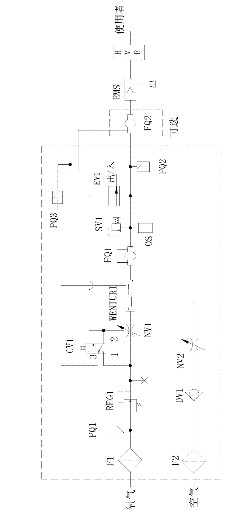
[0025] First, explain the key points of the gas path of the present invention:

[0026] (1) Venturi device and auxiliary pipeline structure, which can inhale air from the bypass, realize the mixing of air and oxygen, and reduce the oxygen concentration;

[0027] (2) The oxygen flow regulating valve NV1 controlled by the gas supply control solenoid valve CV1 adopts a non-serial structure, and the internal diameter of the gas supply control solenoid valve CV1 can be small.

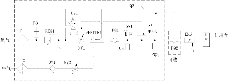
[0028] Second, illustrate the structure of the gas circuit system of a specific embodiment of the present invention:

[0029] The air circuit system of the ventilator and the sensor thereon according to the specific embodiment of the present invention have a structure such as figure 1 As shown, it includes the main air path and its upper branch air path. The main air path includes two inlets and one outlet, which correspond to the oxygen communication pipe, the air communication pipe and the main pipe respe...


PUM


Abstract

The invention relates to a pilot-operated type control air channel system of a breathing machine, which comprises an oxygen communicating pipe, an oxygen flow adjusting valve (NV1), an air communicating pipe, an air inlet one-way valve (DV1), an air flow adjusting valve (NV2), a Venturi device (WENTURI), an air supply control branch air channel and an air supply control electromagnetic valve (CV1). The oxygen flow adjusting valve is arranged on the oxygen communicating pipe, the air inlet one-way valve (DV1) and the air flow adjusting valve (NV2) are arranged on the air communicating pipe, an outlet end of the Venturi device (WENTURI) is communicated with a system external outlet via a main pipe, an inlet end of the Venturi device (WENTURI) is communicated with the oxygen communicating pipe, a bypass of the Venturi device (WENTURI) is communicated with the air communicating pipe, the oxygen communicating pipe is serially communicated with a pressure reduction pump (REG1) and the oxygen flow adjusting valve via air channels from outside to inside, the air supply control electromagnetic valve (CV1) is arranged on the air supply control branch air channel and is serially communicated with the air supply control air channel via an air channel, an inlet end of the air supply control electromagnetic valve is communicated with the oxygen communicating pipe in front of an air inlet end of the oxygen flow adjusting valve via an air channel, an outlet end of the air supply control electromagnetic valve is communicated with a pneumatic control end of the oxygen flow adjusting valve via an air channel, and an exhaust end of the air supply control electromagnetic valve is communicated with the Venturi device or the main pipe via an air channel. The air channel device can adjust oxygen concentration, the small-drift-diameter air supply control electromagnetic valve can be adopted, safety is increased, and the service life of the pilot-operated type control air channel system is prolonged.

Description

technical field [0001] The invention relates to medical electronics, in particular to an air circuit system capable of adjusting oxygen concentration and having a longer service life in a ventilator. Background technique [0002] A ventilator is a device that can replace, control or change a person's normal physiological breathing, increase lung ventilation, improve respiratory function, reduce breathing work consumption, and save heart reserve capacity. It must have the following four basic functions: inflate the lungs, convert inhalation to exhalation, expel alveolar gas, and convert exhalation to inhalation, and repeat in turn. Therefore, the corresponding must have: ⑴ can provide the power to transport gas, instead of the work of human respiratory muscles; ⑵ can produce a certain breathing rhythm, including breathing frequency and breath-inhalation ratio, to replace the function of the human respiratory central nervous system to control the breathing rhythm; ⑶ can Provi...

Claims


Application Information

Patent Timeline
Patent Type & Authority Applications(China)
IPC IPC(8): A61M16/00
Inventor 石露成其新于邦仲
Owner 于邦仲
Why Eureka
Try Eureka