Flood control structure by aid of concrete poles

A technology of cement poles and water-facing surfaces, which is applied in the direction of dikes, dams, coastline protection, etc., can solve the problems of heavy weight, easy collapse, easy subsidence, etc., and achieve the effect of simple structure, wide applicability, and sea tide prevention

Inactive Publication Date: 2013-12-25
沈玉山
View PDF4 Cites 0 Cited by
  • Summary
  • Abstract
  • Description
  • Claims
  • Application Information

AI Technical Summary

Problems solved by technology

[0002] Most of the existing flood control structures are made of stone and cement. The disadvantage is that the resistance to negative pressure caused by the sand on the inside is extremely small, and it is easy to collapse, and the point of action and the direction of the force cannot be adjusted. , It is easy to sink on the wet foundation, causing shaking, bursting, and collapse. The third is to waste a lot of cement and stone
[0003] Although the existing stone and cement-based flood control structures have strengthened the foundation surface or base protection surface, built some barrages, and also reduced the negative pressure inside the river embankment, the collapse phenomenon proves that the embankment cannot be built high. The water-facing surface is similar to the shape of a wall, and the direction and point of action of the force cannot be adjusted due to internal and external entrapment

Method used


Image

  • Flood control structure by aid of concrete poles
  • Flood control structure by aid of concrete poles
  • Flood control structure by aid of concrete poles

Examples


Embodiment Construction

[0020] The present invention will be described in detail below in conjunction with the accompanying drawings and specific embodiments.

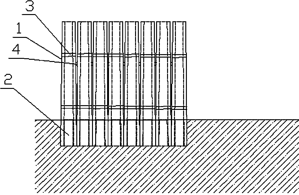
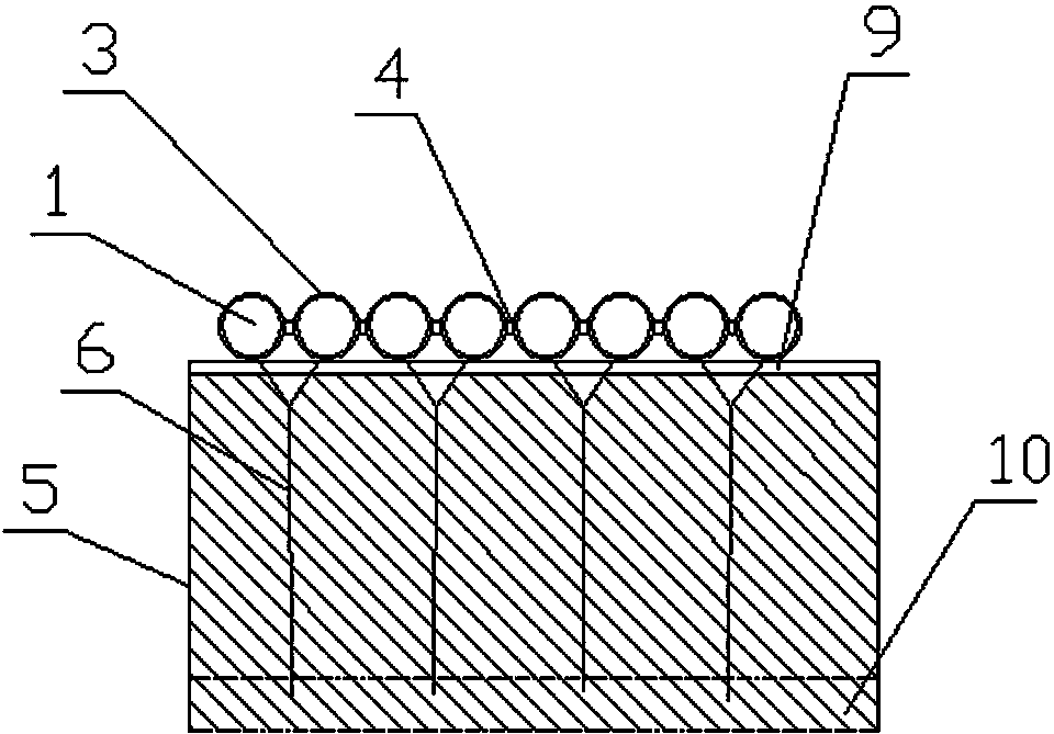
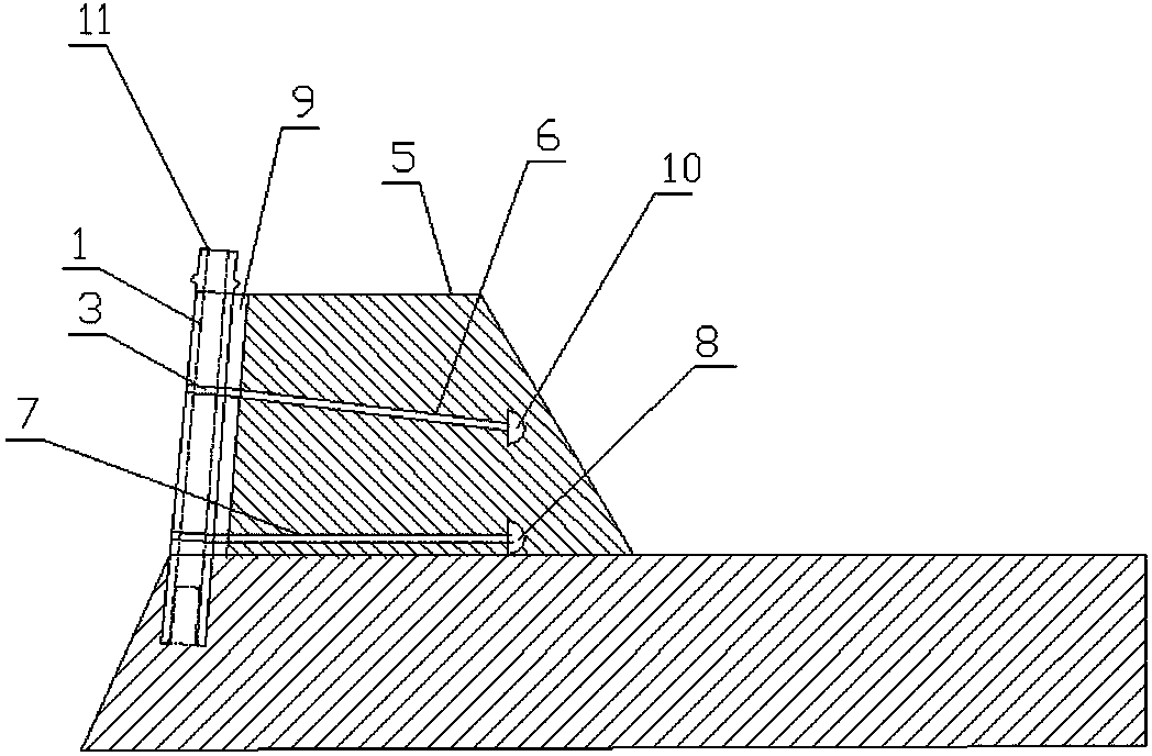
[0021] see figure 1 , 3 , the present invention includes several cement rods 1, cypress piles 2, and sandy soil layers 5, which are thin at the top and thick at the bottom and provided with through holes. The connecting piece 4 is connected, the inner side of the cement rod 1 is provided with a sandy soil layer 5, and a stone plate 9 is arranged between the cement rod 1 and the sandy soil layer 5, a cypress pile 2 is arranged at the bottom of the through hole of the cement rod 1, and the upper part of the cement rod 1 and the lower part are respectively provided with pipe collars 3, and the pipe collars 3 on the top of every two cement rods 1 are respectively connected with one end of the Y-shaped upper drawing object 6, and the other end of the upper drawing object 6 is connected with the fixture 10, and each The pipe hoops 3 at the bottom...


PUM


Abstract

The invention relates to a flood control structure by the aid of concrete poles. A plurality of concrete poles are arranged on an upstream face in parallel, each two adjacent concrete poles are connected via a connecting part, a sand layer is disposed on the inner side of each concrete pole, a stone plate is disposed between each concrete pole and the corresponding sand layer, a cedarwood pile is disposed at the bottom in a through hole of each concrete pole, tube hoops are respectively disposed on the upper portion and the lower portion of each concrete pole, the tube hoops on the upper portions of each two corresponding concrete poles are respectively connected with one end of a Y-shaped upper dragging object, the other end of each upper dragging object is connected with a fixed object, the tube hoops on the lower portions of each two corresponding concrete poles are respectively connected with one end of a Y-shaped lower dragging object, the other end of each lower dragging object is connected with another fixed object, and the upper dragging objects and the lower dragging objects are disposed in the sand layers. The flood control structure can be used for rivers and lakes, further can prevent sea tides, is simple in structure, is beneficial for people for many years once being built, and is light in weight, force directions can be changed, action points are highlighted, and an original so-called integral structure is changed into a combined type integral structure.

Description

technical field [0001] The invention relates to a flood control structure utilizing cement poles. Background technique [0002] Most of the existing flood control structures are made of stone and cement. The disadvantage is that the resistance to negative pressure caused by the sand on the inside is extremely small, and it is easy to collapse, and the point of action and the direction of the force cannot be adjusted. , It is easy to sink on a wet foundation and cause shaking, bursting, and collapse. The third is to waste a lot of cement and stone. [0003] Although the existing stone and cement-based flood control structures have strengthened the foundation surface or base protection surface, built some barrages, and also reduced the negative pressure inside the river embankment, the collapse phenomenon proves that the embankment cannot be built high. The water-facing surface is similar to the shape of a wall, and the direction and point of action of the force cannot be adj...

Claims


Application Information

Patent Timeline
Patent Type & Authority Patents(China)
IPC IPC(8): E02B3/10
Inventor 沈玉山
Owner 沈玉山
Why Eureka
Try Eureka