Multi-frame reciprocating grate

A technology of reciprocating grate and frame, applied in the direction of grate, mobile grate, lighting and heating equipment, etc., can solve problems such as affecting the normal operation of the boiler, connection failure, etc. stable effect

Inactive Publication Date: 2012-06-20
HARBIN INST OF TECH
View PDF3 Cites 5 Cited by
  • Summary
  • Abstract
  • Description
  • Claims
  • Application Information

AI Technical Summary

Problems solved by technology

[0003] The purpose of the present invention is to provide a multi-frame reciprocating grate to solve the problem that the connection between the

Method used


Image

  • Multi-frame reciprocating grate
  • Multi-frame reciprocating grate
  • Multi-frame reciprocating grate

Examples


specific Embodiment approach 1

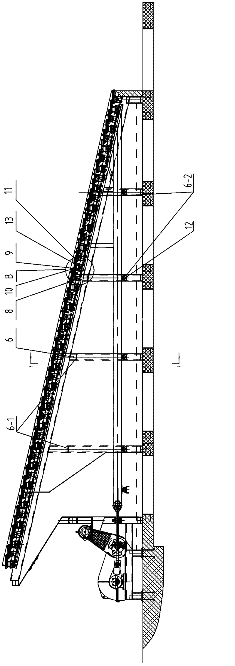
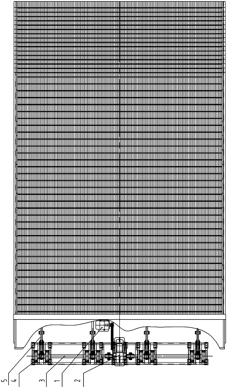
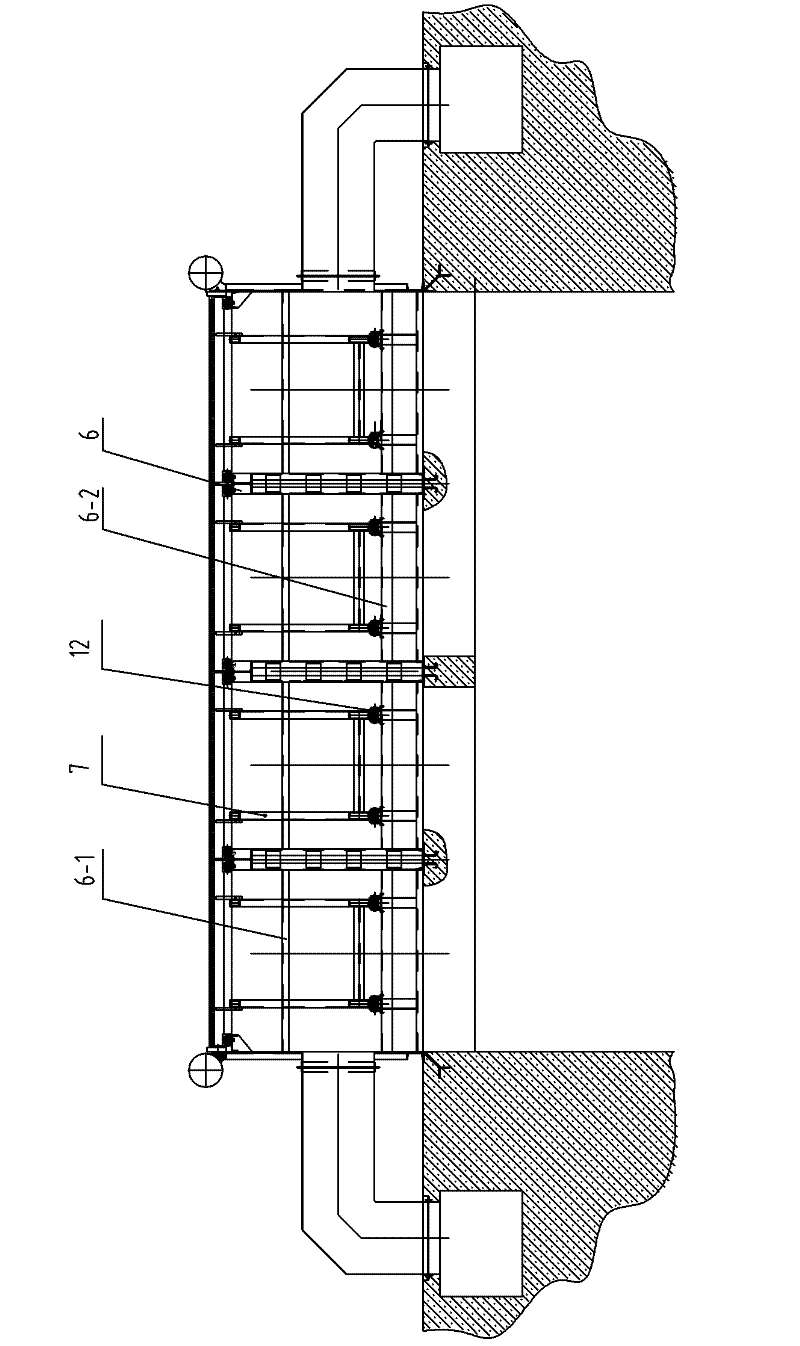
[0007] Specific implementation mode one: combine Figure 1-Figure 4 Describe this embodiment, the fire grate of this embodiment comprises motor 1, speed reducer 2, transmission shaft 3, multiple eccentric wheels 4, multiple push-pull rods 5, fixed fire grate frame 6, movable fire grate frame 7, multiple fixed Grate beam 8, multiple movable grate beams 9, multiple fixed grate pieces 10, multiple movable grate pieces 11, multiple movable grate frame rollers 12 and multiple movable grate beam rollers 13, output end of motor 1 It is connected to the input end of the reducer 2, and the output end of the reducer 2 is connected to the transmission shaft 3. The transmission shaft 3 is equipped with a plurality of eccentric wheels 4, and each eccentric wheel 4 is connected to one end of the push-pull rod 5. The push-pull rod The other end of 5 is connected to the corresponding movable grate frame 7 through transmission, and the movable grate frame 7 is arranged in the fixed grate frame...

specific Embodiment approach 2

[0008] Specific implementation mode two: combination figure 1 To illustrate this embodiment, the fixed grate frame 6 of this embodiment is set with a high front and a low slope at the rear, and the inclination angle is 11°-15°. The use of low-quality coal requires a thick coal seam, and the grate can be guaranteed at an angle of 11°-15°. The reciprocating grate transports a thicker coal seam, and the coal seam has a certain tumbling ability during the movement; the double roller structure decomposes the gravity of the movable grate frame and the movable grate beam to reduce local wear. When a certain roller is worn out, the supported part will sink, and at this moment, another set of rollers can prevent the sinking. Therefore, the structure has the advantages of small running resistance and low failure rate. Other components and connections are the same as those in the first embodiment. Other components and connections are the same as those in the first embodiment.

[0009]...


PUM


Abstract

The invention provides a multi-frame reciprocating grate, relating to a reciprocating grate and aiming at the problem that the abnormal operation of a large-capacity boiler is affected when connection between a grate frame and a grate beam of a reciprocating grate used in the large-capacity boiler at present. According to the invention, an output end of a motor is in transmission connection with an input end of a speed reducer, an output end of the speed reducer is in transmission connection with a transmission shaft, each eccentric wheel is in transmission connection with one end of a push-pull rod, the other end of the push-pull rod is in transmission connection with a corresponding movable grate frame, the movable grate frame is arranged in a fixed grate frame, a fixed grate beam and a movable grate beam are spaced from each other, the movable grate frame is in rolling connection with the fixed grate frame through a plurality of movable grate frame rollers, the fixed grate frame is provided with a plurality of cross beams, a bracket is arranged at the lower part of each cross beam and each movable grate beam roller is arranged in the corresponding bracket and is in rolling connection with the corresponding bracket. The multi-frame reciprocating grate is applicable to a large reciprocating grate boiler.

Description

technical field [0001] The invention relates to a reciprocating grate. Background technique [0002] The working conditions of the reciprocating grate are poor, and there is relative movement between the grates. Due to the influence of the high-temperature fuel layer, the grate pieces are prone to jamming and deformation, which makes the grate beams stressed unevenly and generates additional torque, causing the grate The connection between the frame and the grate beam was damaged, affecting the normal operation of the boiler. This phenomenon becomes more obvious as the boiler capacity increases and the grate width increases. Contents of the invention [0003] The purpose of the present invention is to provide a multi-frame reciprocating grate to solve the problem that the connection between the reciprocating grate frame and the grate beam used on the current large-capacity boiler is damaged and affects the normal operation of the boiler . [0004] The technical scheme a...

Claims


Application Information

Patent Timeline
IPC IPC(8): F23H11/06F23H11/18
Inventor 王威丁立群
Owner HARBIN INST OF TECH
Why Eureka
Try Eureka