Domestic sewage extracting and flushing process in sewage hot pump thermal supplying air conditioner system

A technology for domestic sewage and air conditioning systems, applied in waterway systems, refrigeration and liquefaction, and other non-combustion heat generation, which can solve problems such as environmental discharge, large energy consumption, and pollution

Inactive Publication Date: 2005-05-11
王继柱
View PDF0 Cites 3 Cited by
  • Summary
  • Abstract
  • Description
  • Claims
  • Application Information

AI Technical Summary

Problems solved by technology

These two methods have problems such as large energy consumption, environmental pollution caused by carbon dioxide or smoke emissions during equipment operation, and high maintenance costs.

Method used


Image

  • Domestic sewage extracting and flushing process in sewage hot pump thermal supplying air conditioner system
  • Domestic sewage extracting and flushing process in sewage hot pump thermal supplying air conditioner system

Examples


Embodiment Construction

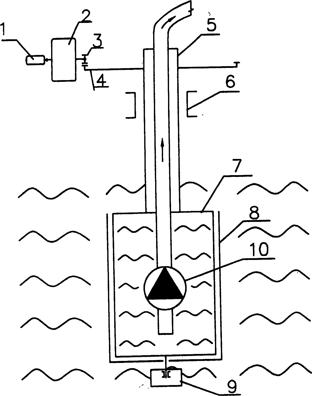
[0009] The domestic sewage extraction and flushing process in the sewage heat pump heating and cooling air-conditioning system of the present invention is realized in this way. figure 1 Schematic diagram of the structure of the domestic sewage extraction device in the heat pump heating and cooling air-conditioning system. In the figure: 1 is the motor, 2 is the reducer, 3 is the gear, 4 is the ring gear, 5 is the cylinder shaft, 6 is the sliding bearing, 7 is the screen body, 8 is the rotating screen, 9 is the sealed sliding bearing, 10 is the sewage pump.

[0010] The motor 1 is connected to the reducer 2, the gear 3 at the output shaft end of the reducer 2 meshes with the ring gear 4, and the sliding bearing 6 is set on the cylinder shaft 5; the rotating screen 8 is set outside the screen body 7, and the screen body 7 slides through the seal The bearing 9 is connected with the rotating screen 8, and the sewage pump 10 is arranged in the screen body 7.

[0011] Turn on the ...


PUM


Abstract

A life sewage extracting and flushing technology for the heating or refrigerating air conditioner system using life sewage as its cold or heat source features that a rotating filter sieve is used to remove the impurities from the life sewage, and after the extracted life sewage flows into plate-type heat exchanger, the backflushing is performed for controlling the dirt deposit.

Description

technical field [0001] The invention relates to a process for extracting and washing domestic sewage in a sewage heat pump heating, cooling and air-conditioning system using domestic sewage as a cold and heat source. Background technique [0002] At present, the traditional central air-conditioning cold and hot water units for cooling in summer and heating in winter have the following three situations: 1. The air source heat pump system mainly consumes electricity, and the cooling-only unit is equipped with electric furnace, oil furnace, and gas furnace. 2. There are lithium bromide direct-fired engines that mainly consume energy, and absorption units that burn diesel, natural gas, gas, etc., steam, hot water, etc., and are heated by heat exchange systems in winter. These two methods have problems such as large energy consumption, environmental pollution caused by carbon dioxide or smoke emission during equipment operation, and high maintenance costs. 3. Ground source heat ...

Claims


Application Information

Patent Timeline
Patent Type & Authority Applications(China)
IPC IPC(8): E03F5/22F24J3/00F25B30/06
Inventor 王继柱
Owner 王继柱
Why Eureka
Try Eureka