Program-control pulse generator used for repetition frequency high-voltage pulse power supply

A high-voltage pulse power supply and pulse generator technology, applied in the field of pulse generators, can solve problems that affect the safe and reliable triggering of power switching elements, difficult adjustment of pulse frequency and pulse amplitude, tailing or recoil, etc., to achieve superior real-time performance , Powerful peripheral functions, easy to upgrade the effect

Active Publication Date: 2012-06-20
INST OF ELECTRICAL ENG CHINESE ACAD OF SCI
View PDF6 Cites 23 Cited by
  • Summary
  • Abstract
  • Description
  • Claims
  • Application Information

AI Technical Summary

Problems solved by technology

[0003] Pulse generators have been developed for many years, among which the method of controlling circuits based on frequency dividers and crystal oscillators and using LC oscillator circuits to generate pulses was the first to be developed. The disadvantage is that it is not easy to generate narrower and better-shaped pulse signals. These The pulse generated by the generator will also have a tail or recoil, which directly affects the safe and reliable triggering of the power switching element; and the pulse generator that directly relies on a simple combination of discrete components to generate pulse signals, pulse frequency and pulse amplitude, etc. Difficult to adjust, such as the "programmable synchronous pulse generator" of the patent CN200510089523.9, which can run in a clock synchronizer, using phase detection and verification circuit system to ensure the pulse edge; relying on programmable embedded chips to generate high-demand pulses Signal has become the best choice - generator based on FPGA programming device
Representatives such as Masahiro Akiy

Method used


Image

  • Program-control pulse generator used for repetition frequency high-voltage pulse power supply
  • Program-control pulse generator used for repetition frequency high-voltage pulse power supply
  • Program-control pulse generator used for repetition frequency high-voltage pulse power supply

Examples


Embodiment Construction

[0016] The present invention is further described below with reference to the accompanying drawings and specific embodiments.

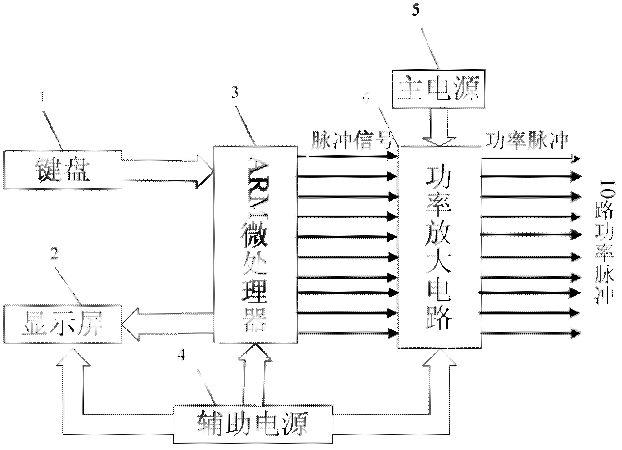
[0017] like figure 1 As shown, the present invention mainly includes a main power supply 5 , an auxiliary power supply 4 , an ARM microprocessor 3 and a power amplifier circuit 6 .

[0018] The working process of the generator of the present invention is: the command is transmitted to the ARM microprocessor 3 from the keyboard through the transmission line, and the parameter data set is displayed to the user through the display screen 2 at the same time, and the ARM microprocessor 3 generates multiple pulses under the instruction Signals can have ten pulse signal outputs at most, and the time delay between the ten pulse signals can be adjusted. The pulse signal output by the ARM microprocessor 3 is amplified by the power amplifier circuit 6, and the output pulse amplitude is adjusted by the main The power supply 5 completes, and the output power puls...


PUM


Abstract

A program-control pulse generator used for a repetition frequency high-voltage pulse power supply comprises an ARM (advanced RISC machine) microprocessor (3), a main power supply (5), an auxiliary power supply (4) and a power amplifying circuit (6). Functions of inputting 220V-voltage alternating current and outputting 1V to 15V voltage after rectifying, filtering and pulse transforming and transforming adjustment are realized by a main structure of the main supply (5). Functions of power factor correction and voltage stabilizing control of the main power supply are realized by a main power supply voltage control circuit of the main power supply (5). A 5V voltage output end and a 1V to 15V voltage output end of the main power supply (5) are connected to a power supply pin and a data receiving pin of the ARM microprocessor (3) through leads and are connected to an input end of the power amplifying circuit (6) from an I/O (input/output) output pin of the ARM microprocessor. The auxiliary power supply (4) stabilizes the 5V voltage and the 15V voltage and provides power for driving the ARM microprocessor (3) and an IGBT (insulated gate bipolar translator), and the power amplifying circuit (6) provides trigger signals for a driver of a switch device.

Description

technical field [0001] The invention relates to a pulse generator. Background technique [0002] High-voltage pulse power supply is a power supply device through low-speed storage and high-speed release of energy, and outputs high-voltage pulses with a certain width, amplitude and frequency through the opening and closing of various forms of switches. At present, high-voltage pulse power supplies are mainly used in basic research fields such as gas discharge, dielectric insulation aging, and pulse jet mechanism, as well as industrial application fields such as material surface modification, wastewater / gas treatment, and sterilization. In experimental research, parameters such as pulse width, frequency, and amplitude need to be changed to analyze the impact of various power supply parameters on different discharge forms. In industrial applications, parameters such as pulse width, frequency, and amplitude need to be changed to deal with different processing objects. However, ...

Claims


Application Information

Patent Timeline
IPC IPC(8): H02M9/06
Inventor 邵涛李文峰章程严萍
Owner INST OF ELECTRICAL ENG CHINESE ACAD OF SCI
Why Eureka
Try Eureka