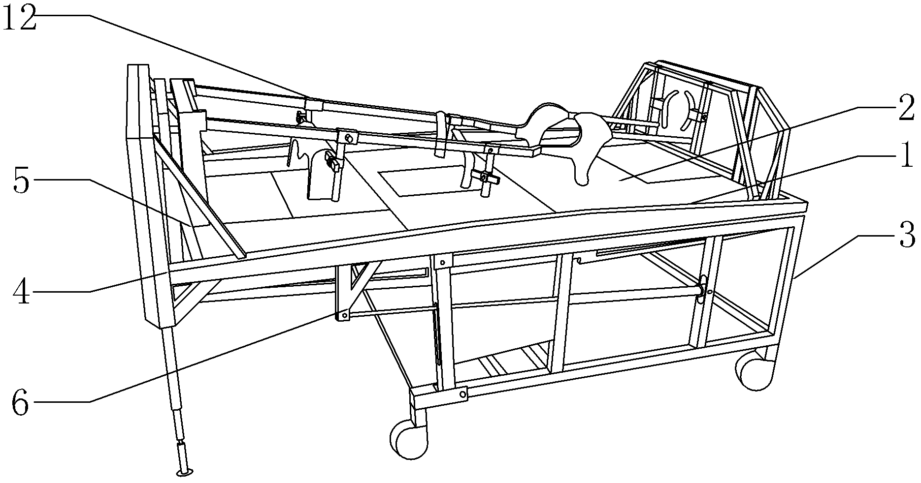
Nursing bed
A nursing bed and bed frame technology, applied in the field of nursing beds, can solve the problems of troublesome nursing staff wiping the patient's back, the patient cannot experience the feeling of standing, and the operation is not very convenient, and achieves low cost of mechanical structure and labor-saving operation. , the effect of simple structure
- Summary
- Abstract
- Description
- Claims
- Application Information
AI Technical Summary
Problems solved by technology
Method used
Image
Examples
Embodiment 1
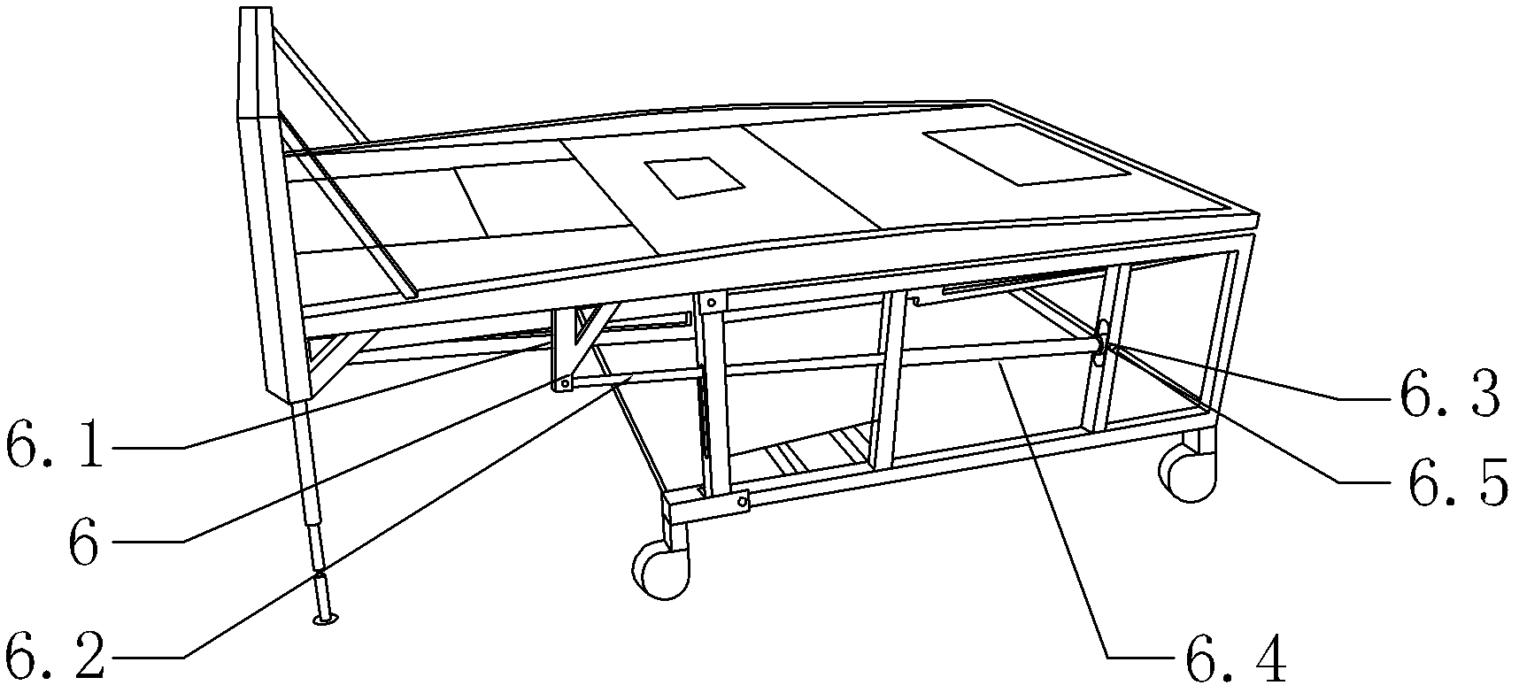
[0035] Such as image 3The shown standing driving device 6 includes a stretching arm 6.1 arranged under the front end of the stand 4, a standing driving screw 6.2 fixed on the stretching arm 6.1 by a pin, and a standing rotating device 6.3 matched with the standing driving screw 6.2. The rotating device 6.3 includes a rotating tube with a nut 6.4 and a standing rotating bearing 6.5, the rotating tube with a nut 6.4 has a nut end sleeved on the driving screw 6.2 standing, and the standing rotating bearing 6.5 is set on the rotating tube with a nut 6.4 without a nut end and is fixed Connection, the standing rotary bearing 6.5 is connected with the support frame 3 through the hinge shaft as image 3 Shown; the front top of the standing frame 4 is provided with a telescopic link 11; the telescopic link 11 is connected with the standing frame 4 through a pin shaft, so that the telescopic link can rotate around the pin shaft, and the telescopic link 11 is provided with a suspension ...
Embodiment 2
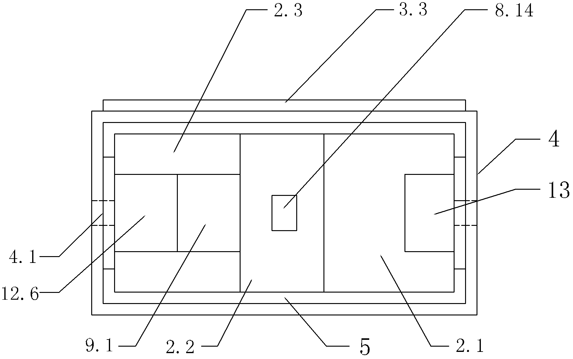
[0038] Such as figure 2 and Figure 5 The shown rollover driving device 7 includes a rollover rotary bearing 7.6 fixed on the stand frame 4 by a pin shaft, a rollover drive screw 7.1, a worm gear reducer 7.2 and a semicircular belt fixed on the center of the front end of the rollover frame 5 The toothed arc groove 7.3, the rollover drive screw 7.1 is the input end of the worm gear reducer 7.2, the output end of the worm gear reducer 7.2 is a spur gear 7.4 and cooperates with the semicircular toothed arc groove 7.3 as Figure 9 As shown; the front end of the standing frame 4 is provided with bayonet pin 7.5 and is connected with the standing frame 4 by a pin shaft, and the rollover frame 5 is provided with a protrusion 5.1 that wants to cooperate with the bayonet pin 7.5; when the nursing bed needs a rollover posture, the nursing staff first Rotate the bayonet 7.5 to the horizontal position, then remove the figure 2 The auxiliary bed 3.3 shown on the outside of the support ...
Embodiment 3
[0040] Such as Figure 4 , Figure 14 and Figure 15 The shown bedpan lifting device 8 includes a frame 8.1, a driving device 8.2 and a lifting device 8.3, and the driving device 8.2 includes a lifting driving screw 8.4, which is sleeved on the lifting driving screw 8.4 and connected to the frame 8.1 through a hinge shaft. Figure 4 and Figure 14 The rotating bearing 8.5 shown, the lifting rotating tube 8.6 with nuts sleeved on the lifting drive screw 8.4, the connecting rod 8.7 fixed at the end of the lifting rotating tube 8.6 with nuts through the pin shaft, fixed at the end of the connecting rod 8.7 and perpendicular to it The cross bar 8.8, parallel to the connecting rod 8.7 and fixed on the inner side of the bottom end of the frame 8.1 through the pin shaft push rod 8.9, the extension bar 8.10 fixed on the lower end surface of the cross bar 8.8 and the extension bar 8.10 fixed on the bottom end of the frame through the pin shaft The front frame push rod 8.11 at the en...
PUM
 Abstract
Description
Claims
Application Information
 - R&D
- Intellectual Property
- Life Sciences
- Materials
- Tech Scout
- Unparalleled Data Quality
- Higher Quality Content
- 60% Fewer Hallucinations
Browse by: Latest US Patents, China's latest patents, Technical Efficacy Thesaurus, Application Domain, Technology Topic, Popular Technical Reports.
© 2025 PatSnap. All rights reserved.Legal|Privacy policy|Modern Slavery Act Transparency Statement|Sitemap|About US| Contact US: help@patsnap.com


