
Double stroke lateral-push sliding mechanism bending die

A technology of bending molds and bending blocks, which is applied in metal processing equipment, forming tools, manufacturing tools, etc., can solve problems such as unsolvable mold structures, waste of mold development costs, and increased mold inventory, so as to improve operating efficiency and structure Simplicity and the effect of improving processing efficiency

Inactive Publication Date: 2012-06-27
KUSN SHENGTAI ELECTROMECHANICAL MFG
View PDF6 Cites 14 Cited by
  • Summary
  • Abstract
  • Description
  • Claims
  • Application Information

AI Technical Summary

Problems solved by technology

[0002] In the current common sheet metal bending, it is common to form / bend two sides at one time; usually such molds use simple two-point positioning, or use internal positioning for stamping and bending, that is If it is bent into a right angle, it needs to be folded into a hypotenuse first, and then bent into a right angle through another mold or another operation. The general mold structure of bending forming cannot solve the problem
In this regard, correspondingly, multiple sets of bending molds must be opened, which not only wastes mold development costs, but also increases mold inventory
Once the product design is changed, it will cause unnecessary waste

Method used


Image

  • Double stroke lateral-push sliding mechanism bending die
  • Double stroke lateral-push sliding mechanism bending die

Examples


Embodiment Construction

[0017] In order to make the technical means, creative features, goals and effects achieved by the present invention easy to understand, the present invention will be further described below in conjunction with specific embodiments.

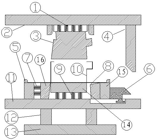
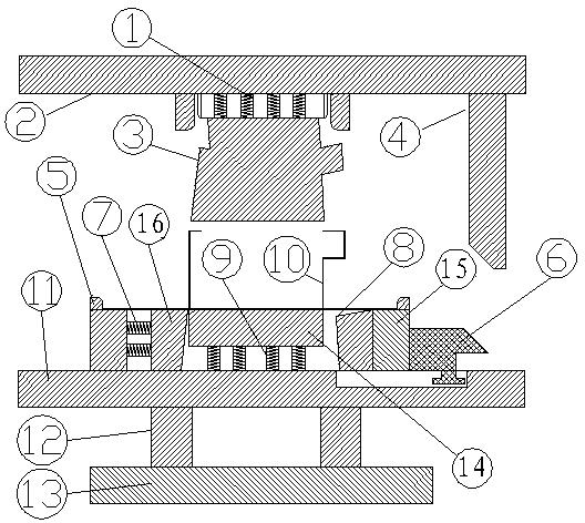
[0018] see figure 1 , the side pushing slider mechanism bending mold of the present embodiment includes an upper die base 2, a lower die base 11 adapted to the upper die base 2 and an upper stripping plate 3 installed on the upper die base 2; 11 is installed with a lower template 14 for placing the material sheet 10 to be bent, and a lower pad 12 and a lower pad 13 are installed at the bottom of the lower mold base 11, and the lower pad 12 is arranged on the lower mold base 11 and the lower pad 13 In between, the lower mold base 11 is also equipped with a bending block 8 for bending the material sheet 10 to be bent and a side pushing slider 7 that drives the bending block 8 to move. The bending block 8 and the side pushing slider 7 It is arranged...


PUM


Abstract

The invention relates to a lateral-push sliding block mechanism bending die which comprises an upper die seat, a lower die seat matched with the upper die seat, and an upper stripper arranged on the upper die seat, wherein a lower die plate used for the placement of bending material pieces is arranged on the lower die seat, a lower cushion block and a lower bearing plate are mounted at the bottom of the lower die seat, the lower cushion block is arranged between the lower die seat and the lower bearing plate, and a bending block used for bending material pieces to be bent, and a lateral-push sliding block for driving the bending block to move are arranged on the lower die seat; a bending and leaning knife used for extruding the lateral-push slide block to move is further mounted on the upper die seat during the die assembly of the upper die seat and the lower die seat, an upper die spring is further arranged between the upper stripper and the upper die seat, and a lower die spring is further arranged between the lower die plate and the lower die seat. The lateral-push sliding block mechanism bending die provided by the invention has a simple structure, and lowers and reduces the costs for die development and die obsolete materials. The working performance is improved greatly, actions in die replacement to punching equipment are reduced, and the processing efficiency of the equipment is improved.

Description

technical field [0001] The invention relates to a bending die, in particular to a bending die for a side push slider mechanism, which is a set of practical dies for sheet metal bending. Background technique [0002] In the current common sheet metal bending, it is common to form / bend two sides at one time; usually such molds use simple two-point positioning, or use internal positioning for stamping and bending, that is If it is bent into a right angle, it needs to be folded into a hypotenuse first, and then bent into a right angle through another mold or another operation. The general mold structure of bending forming cannot be solved. In this regard, correspondingly, multiple sets of bending molds must be opened, which not only wastes mold development costs, but also increases mold inventory. Once the product design is changed, it will cause unnecessary waste. Contents of the invention [0003] Aiming at the deficiencies in the prior art, the purpose of the present inv...

Claims


Application Information

Patent Timeline
Patent Type & Authority Applications(China)
IPC IPC(8): B21D37/10B21D5/06
Inventor 杨天文
Owner KUSN SHENGTAI ELECTROMECHANICAL MFG
Learn More