Turning-milling combined machine tool and spindle locking device thereof

A locking device and compound machine tool technology, applied in the field of mechanical processing, can solve the problems of easily damaged rear bearings and large axial loads, and achieve the effects of simplified structure, small structural size, and direct and effective locking

Inactive Publication Date: 2012-06-27
SANY GRP
View PDF6 Cites 17 Cited by
  • Summary
  • Abstract
  • Description
  • Claims
  • Application Information

AI Technical Summary

Problems solved by technology

[0005] The purpose of the present invention is to provide a turning-milling compound machine tool and its spindle locking device to solve the problem that the rear bearing of the turning-milling compound machine tool using a tapered surface locking device in the prior art bears a large axial load and the rear bearing is easily damaged. question

Method used


Image

  • Turning-milling combined machine tool and spindle locking device thereof
  • Turning-milling combined machine tool and spindle locking device thereof
  • Turning-milling combined machine tool and spindle locking device thereof

Examples


Embodiment Construction

[0020] It should be noted that, in the case of no conflict, the embodiments in the present application and the features in the embodiments can be combined with each other. The present invention will be described in detail below with reference to the accompanying drawings and examples.

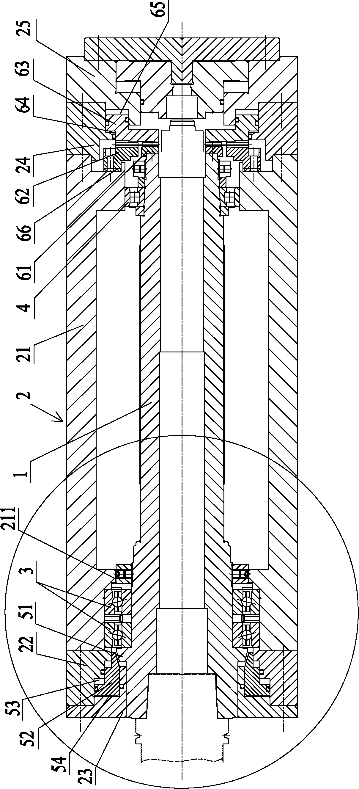
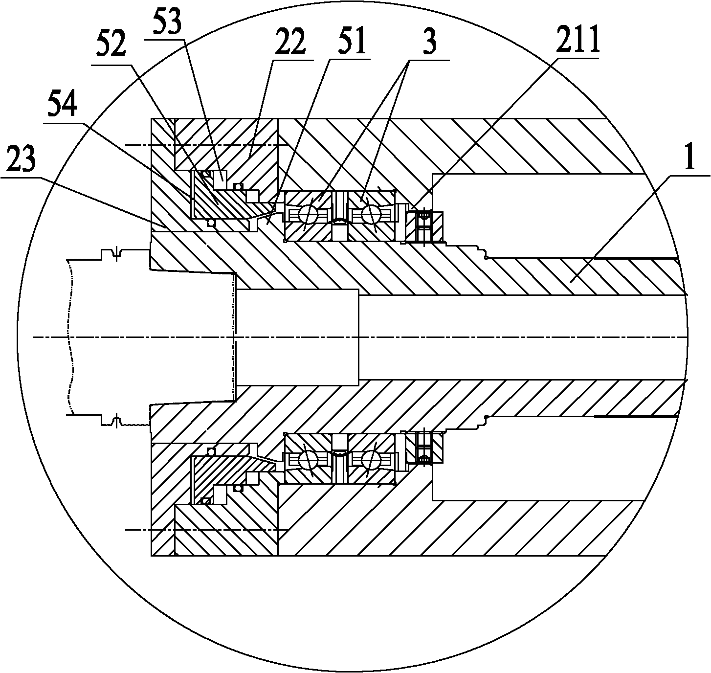
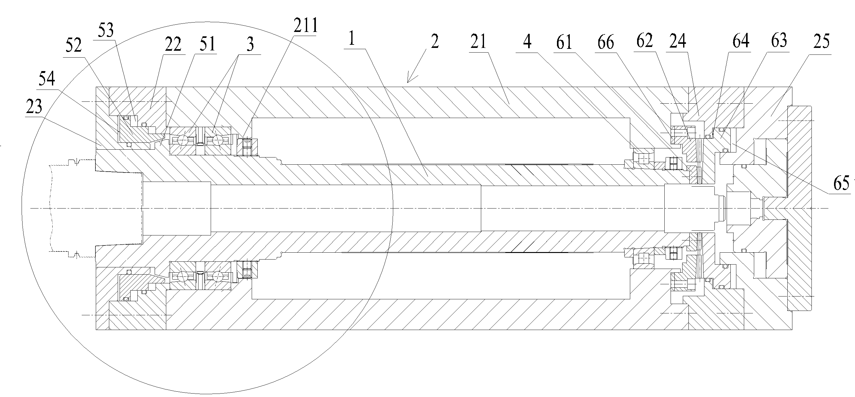
[0021] see figure 1 with figure 2 , shows the structure of the spindle locking device of the turning-milling compound machine tool provided by the present invention. The main shaft 1 is installed in the main shaft housing 2 , and the two ends of the main shaft 1 are respectively connected with the main shaft housing 2 through the first bearing 3 and the second bearing 4 . It should be noted that, usually we take figure 1 The end where the first bearing 3 is located is called the front end of the main shaft 1, and the first bearing 3 is called the front bearing. Correspondingly, the end where the second bearing 4 is located is called the rear end of the main shaft 1, and the second bearing ...


PUM


Abstract

The invention provides a turning-milling combined machine tool and a spindle locking device thereof. The spindle locking device comprises end face tooth locking devices arranged in a spindle box and close to the outer side of a second bearing and a conical surface locking device arranged in the spindle box and close to a first bearing, the conical surface locking device comprises a fixed locking annular block fixed on a spindle and a movable locking annular block capable of sliding axially along the spindle, the periphery of the fixed locking annular block is a conical surface, and an inner hole at one end of the movable locking annular block toward the fixed locking annular block is a conical surface. When the turning-milling combined machine tool is in a turning state, the end surface tooth locking devices are engaged mutually, so that the conical surface locking device achieves locking, and locking of the spindle is ensured through the two locking mechanisms. When the spindle is in a milling state, the two locking mechanisms relax simultaneously, and rotation of the spindle can be achieved. The spindle locking device is high in accuracy, good in manufacturability and simple in structure.

Description

technical field [0001] The invention relates to the field of mechanical processing, and more specifically, to a turning-milling compound machine tool and a spindle locking device thereof. Background technique [0002] The turn-milling machine tool has attracted extensive attention for its flexible production capacity with a universal processing range. Its core is the integrated milling spindle technology with both milling and turning capabilities. When the turn-mill machine tool is in the milling state, the spindle can rotate; when the turn-mill machine tool is in the turning state, the spindle needs to be locked so that the spindle does not move. At present, there are mainly two solutions to realize the conversion of the two functions of turning and milling. [0003] One solution is to use end sprockets for locking. That is, the front end of the main shaft (the front end of the main shaft refers to the end of the main shaft close to the processing tool) is locked by an en...

Claims


Application Information

Patent Timeline
Patent Type & Authority Applications(China)
IPC IPC(8): B23B19/02B23P23/02
Inventor 赖修颖许蒲双王波
Owner SANY GRP
Why Eureka
Try Eureka