
Collapsible power-driven table stand

a power-driven, table-top technology, applied in the direction of sectional furniture, variable height tables, furniture parts, etc., can solve the problems of poor effectiveness of these tables, large differences in the height of the table, drawbacks of complicated structures, etc., to save packaging materials, reduce transportation costs, and reduce the overall size of the structure after collapsing

Active Publication Date: 2015-10-08
TIMOTION TECH CO LTD +1
View PDF37 Cites 29 Cited by
  • Summary
  • Abstract
  • Description
  • Claims
  • Application Information

AI Technical Summary

Benefits of technology

The present invention is a collapsible power-driven table stand that simplifies assembly and has a compact structure for reducing size. The stand has bendable and extendable legs, which allows for easy assembly and disassembly. The overall size of the structure after collapsing can be significantly reduced to save on packaging materials and transportation costs. The stand also has a beautiful appearance with concealed driving members and controllers.

Problems solved by technology

Although these tables have the characteristic of simplified assembly in their structures, due to the lifting of the pneumatic cylinders at high speed in the operation as well as the requirement of the manual actions of lowering the pneumatic cylinders by the user during the lowering thereof, improper forces exerted by the user can often lead to extremely large differences in the heights of the table, which cannot satisfy the needs of the user and often requires numerous attempts on the adjustments of lifting and lowering until a suitable height of the table can be obtained; in other words, the effectiveness of these tables are poor.
Although such solution can effectively overcome the difficulties in the aforementioned adjustments on the positions of the heights of the tables, it has the drawbacks of a complicated structure, tedious and time-consuming assembly, heavy weight, large size and so on, that need to be overcome.

Method used


Image

  • Collapsible power-driven table stand
  • Collapsible power-driven table stand
  • Collapsible power-driven table stand

Examples


Embodiment Construction

[0018]The following provides detailed description of embodiments of the present invention along with the accompanied drawings. It can, however, be understood that the accompanied drawings are provided for illustrative purposes only and shall not be treated as limitations to the present invention.

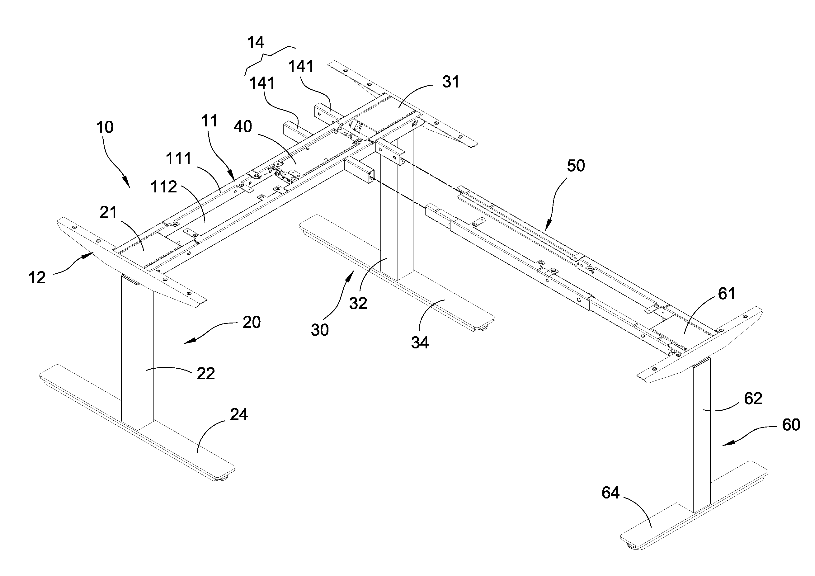
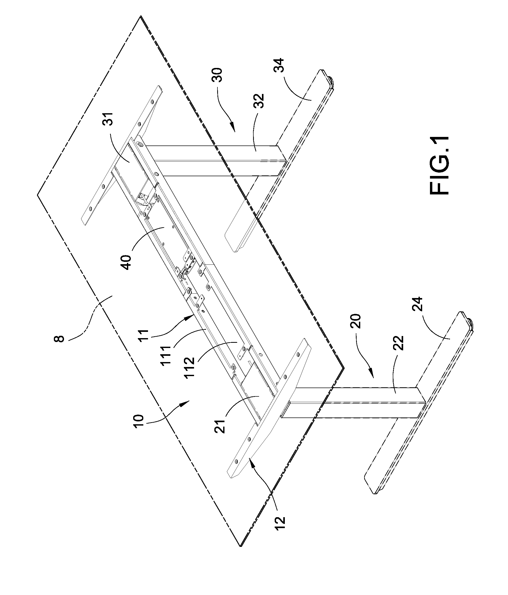
[0019]Please refer to FIG. 1 to FIG. 4. The present invention provides a collapsible power-driven table stand mainly comprising a supporting body 10, a first stand 20 and a second stand 30.

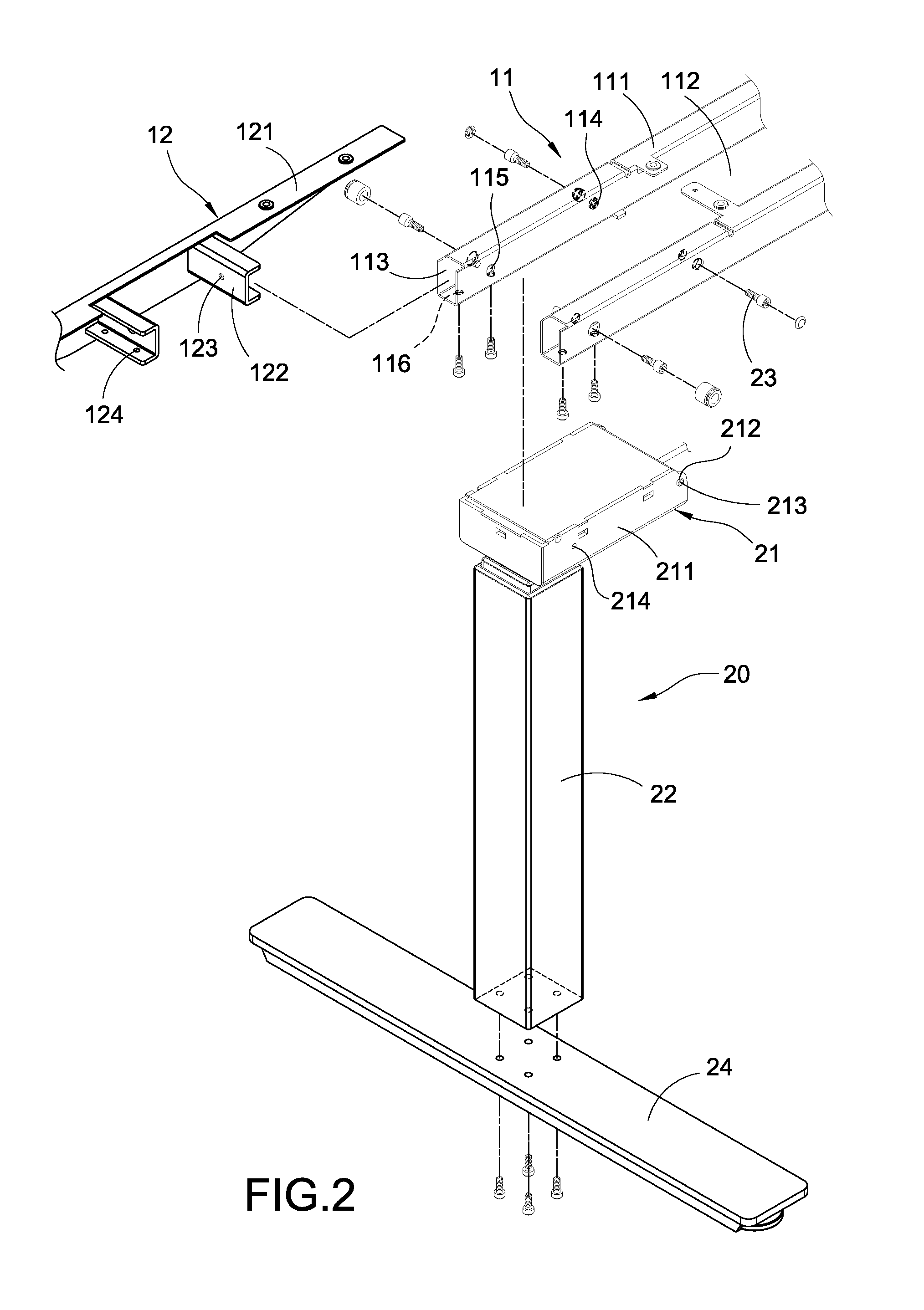
[0020]The supporting body 10 is of an elongated shape and mainly comprises a lateral bracket 11 and two side wings 12. The lateral bracket 11 includes two rectangular columns 111 spaced apart from each other and connected in parallel; a receiving slot 112 is formed between the two rectangular columns 111; two end surfaces of each rectangular column 111 include a rectangular insertion hole 113 formed thereon respectively. In addition, each side plate of the rectangular column 111 includes an inner side hole...


PUM


Abstract

A collapsible power-driven table stand includes a supporting body of an elongated shape, a first stand having a first driving member and a plurality of first extendable rods driven by the first driving member to move axially relative to each other and a second stand having a second driving member and a plurality of second extendable rods driven by the second driving member to move axially relative to each other. The first diving member is pivotally attached to one end of the supporting body and the second diving member is also pivotally attached to another end of the supporting body in order to allow both the first and second stands to extend / collapse relative to the supporting body. Accordingly, the assembly of the collapsible power-driven table is simplified and the overall size thereof is reduced.

Description

BACKGROUND OF THE INVENTION[0001]1. Field of the Invention[0002]The present invention is related to a power-driven table stand, in particular, to a collapsible power-driven table stand.[0003]2. Description of Related Art[0004]Ergonomic designs are known to be the design trend based on the concept associated with human bodies and shapes such that the design is able to provide the most optimal solution according to different shape and sizes of the user; therefore, mass produced products can also be incorporated into various types of adjustment structures therein for its use in order to satisfy the needs of different users. Among these products, the lifting mechanism of table is also one of the realizations for the application of the ergonomic design, which is able to adjust the height of the table in order to suit to the needs of different body heights and to achieve most optimal comforts. Therefore, the table with lifting function with adjustments has become one of the main trends in...

Claims


Application Information

Patent Timeline
Patent Type & Authority Applications(United States)
IPC IPC(8): A47B1/08A47B1/10
CPCA47B1/10A47B1/08A47B3/08A47B9/20A47B13/06A47B87/002A47B2200/0056A47B2200/0061A47B3/002A47B9/00A47B13/02A47B19/08A47B2003/0821A47B2003/0827
Inventor WU, CHOU-HSIN
Owner TIMOTION TECH CO LTD
Learn More