Mounting arrangement for optical devices

a technology for mounting arrangements and optical devices, applied in the direction of cameras, building scaffolds, domestic objects, etc., can solve the problems of additionally lacking flexibility in mounting arrangements with respect, and achieve the effects of low weight, high reliability, and good handling ability

Active Publication Date: 2010-07-22
VOGT PHILIPPE
View PDF23 Cites 24 Cited by
  • Summary
  • Abstract
  • Description
  • Claims
  • Application Information

AI Technical Summary

Benefits of technology

[0007]The present invention creates a mounting arrangement which is of lower weight than the known arrangements and is also more flexible for receiving different clamping plates. The good handling capability and high level of reliability are retained.

Problems solved by technology

Although, over the years, this mechanism has proved to be reliable and convenient to handle, such mounting arrangements are relatively heavy and the mounting arrangement additionally lacks flexibility with respect to different clamping plates since these must be precisely matched to the dovetail guide.

Method used


Image

  • Mounting arrangement for optical devices
  • Mounting arrangement for optical devices
  • Mounting arrangement for optical devices

Examples


Embodiment Construction

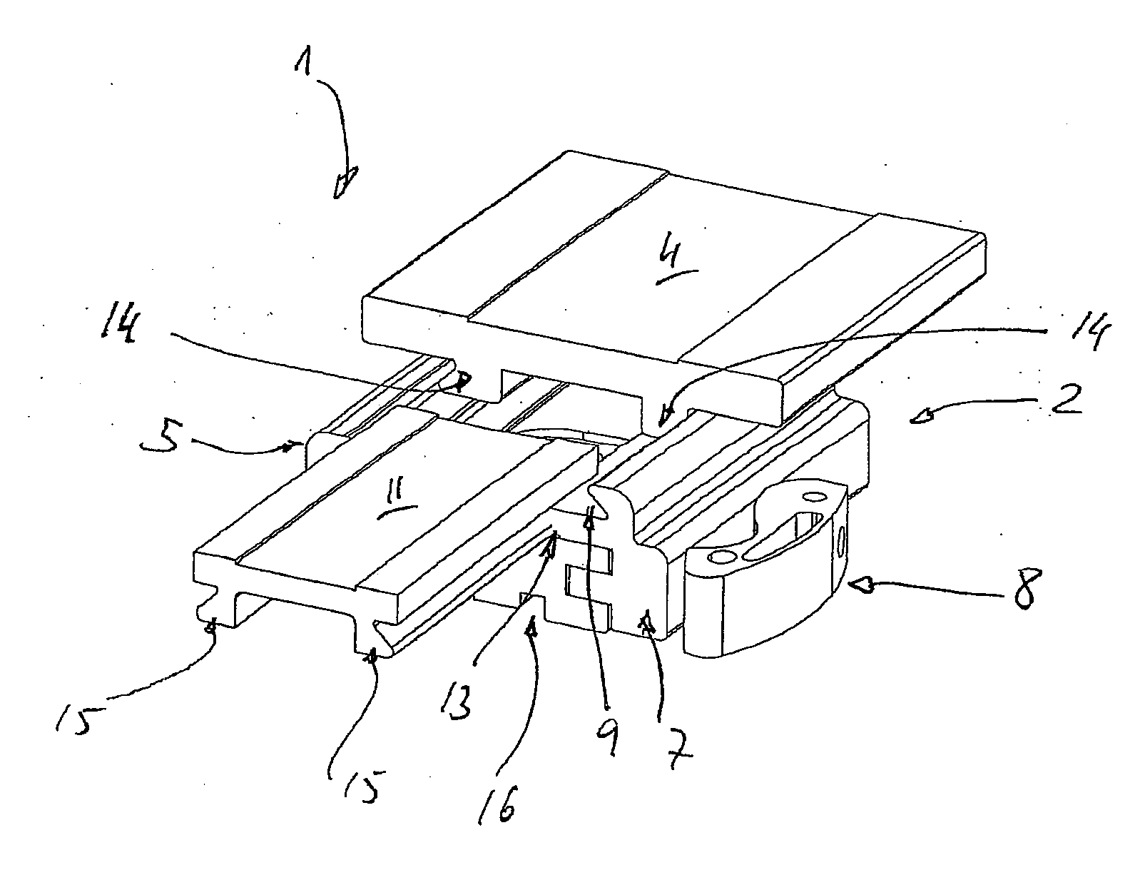
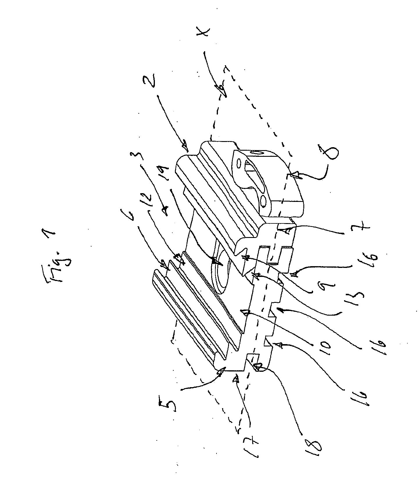
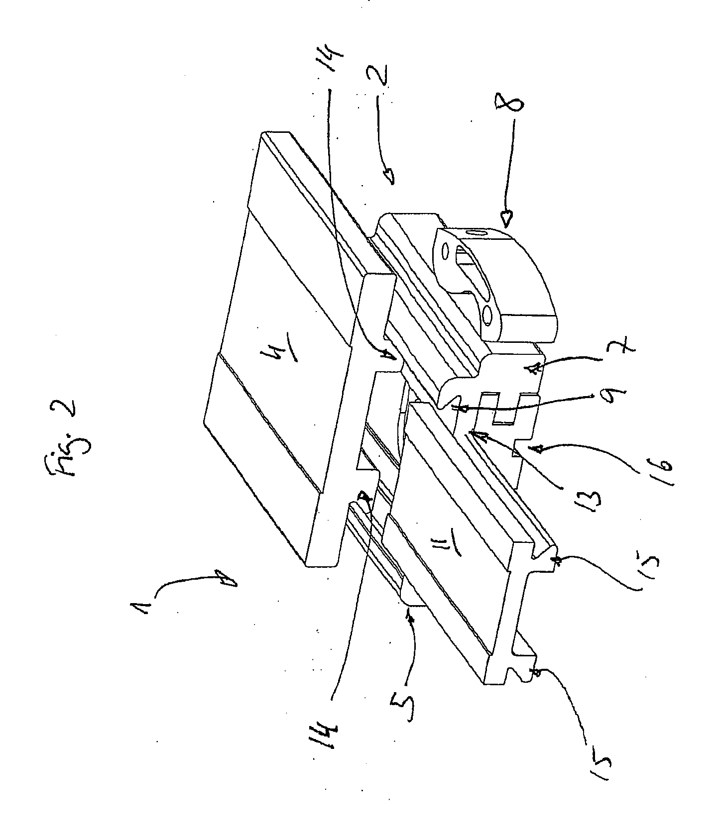
[0023]Referring now to the drawing and the illustrative embodiments depicted therein, a mounting arrangement, designated as a whole by 1, for optical devices is shown. The mounting arrangement 1 has a mounting plate 2 which has a first dovetail-like undercut guide 3 to receive a large clamping plate 4 (see FIG. 2 in which it is partially inserted from the rear in the viewing direction).

[0024]The mounting plate 2 may be substantially of rectangular plate-shaped form and spans a plane X which passes through it. The mounting plate 2 has a lateral web 5, in which an undercut dovetail profiled groove 6 is formed, which forms one side of the guide 3. On the opposite side of the mounting plate 2, a strip 7 is provided which is moveably connected to the mounting plate 2 via a clamping mechanism 8 and forms a second undercut dovetail profiled groove 9 of the guide 3.

[0025]The dovetail profiled grooves 6 and 9 thus together form the first undercut guide 3 which lies on one side of the plane X...


PUM


Abstract

The invention relates to a mounting arrangement for optical devices having a mounting plate forming an undercut guide for receiving a clamping plate, the mounting plate comprising a side bar in which an undercut profile groove is formed, and having a strip located opposite the bar movably connected to the mounting plate via a clamping mechanism and a second undercut profile groove forming the undercut guide together with the first undercut profile groove, the strip being able to be tightened against the mounting plate by the clamping mechanism to fix the clamping plate, whereby the spacing distance between the undercut profile grooves is reduced. A second undercut guide is formed by additional undercut profile grooves in the same side bar of the mounting plate and the same strip, wherein the guides are both disposed on one side of the plane (X) spanned by the mounting plate.

Description

[0001]The invention relates to a mounting arrangement for optical devices and, in particular, to a mounting arrangement having a mounting plate which forms an undercut guide in order to receive a clamping plate, wherein the mounting plate has a lateral web, in which an undercut profiled groove is formed, and having a strip opposite the web, which is moveably connected to the mounting plate by a clamping mechanism and has a second undercut profiled groove which, together with the first undercut profiled groove, forms the undercut guide, wherein the strip for fixing the clamping plate can be pulled against the mounting plate by the clamping mechanism, whereby the spacing between the undercut profiled grooves is reduced.[0002]Such mounting arrangements are known for rapidly changing optical devices on stands, which permit non-screwed connection of the optical device to the stand, etc. These mounting devices, also known as quick-change adaptor systems, offer a quick-change facility in a...

Claims


Application Information

Patent Timeline
Patent Type & Authority Applications(United States)
IPC IPC(8): F16M13/00
CPCF16M11/04F16M11/041G03B17/56G02B7/00F16M2200/027G03B17/566
Inventor VOGT, PHILIPPE
Owner VOGT PHILIPPE
Why Eureka
Try Eureka