Device for laying a flexible material web

A technology of flexible materials and material belts, which is applied in the field of flexible material belt stacking devices, can solve problems such as inability to move laterally, and achieve the effects of small structural costs, reduced quality and structural size, and material savings

Inactive Publication Date: 2006-11-29
SAURER GMBH & CO KG
View PDF4 Cites 28 Cited by
  • Summary
  • Abstract
  • Description
  • Claims
  • Application Information

AI Technical Summary

Problems solved by technology

However, the stacking rollers known from DE 298 23 580 U1 are not part of the stacking trolley - and as in the above-mentioned prior art - have the same width dimension as the stacking point, and in addition cannot move laterally

Method used


Image

  • Device for laying a flexible material web
  • Device for laying a flexible material web
  • Device for laying a flexible material web

Examples


Embodiment Construction

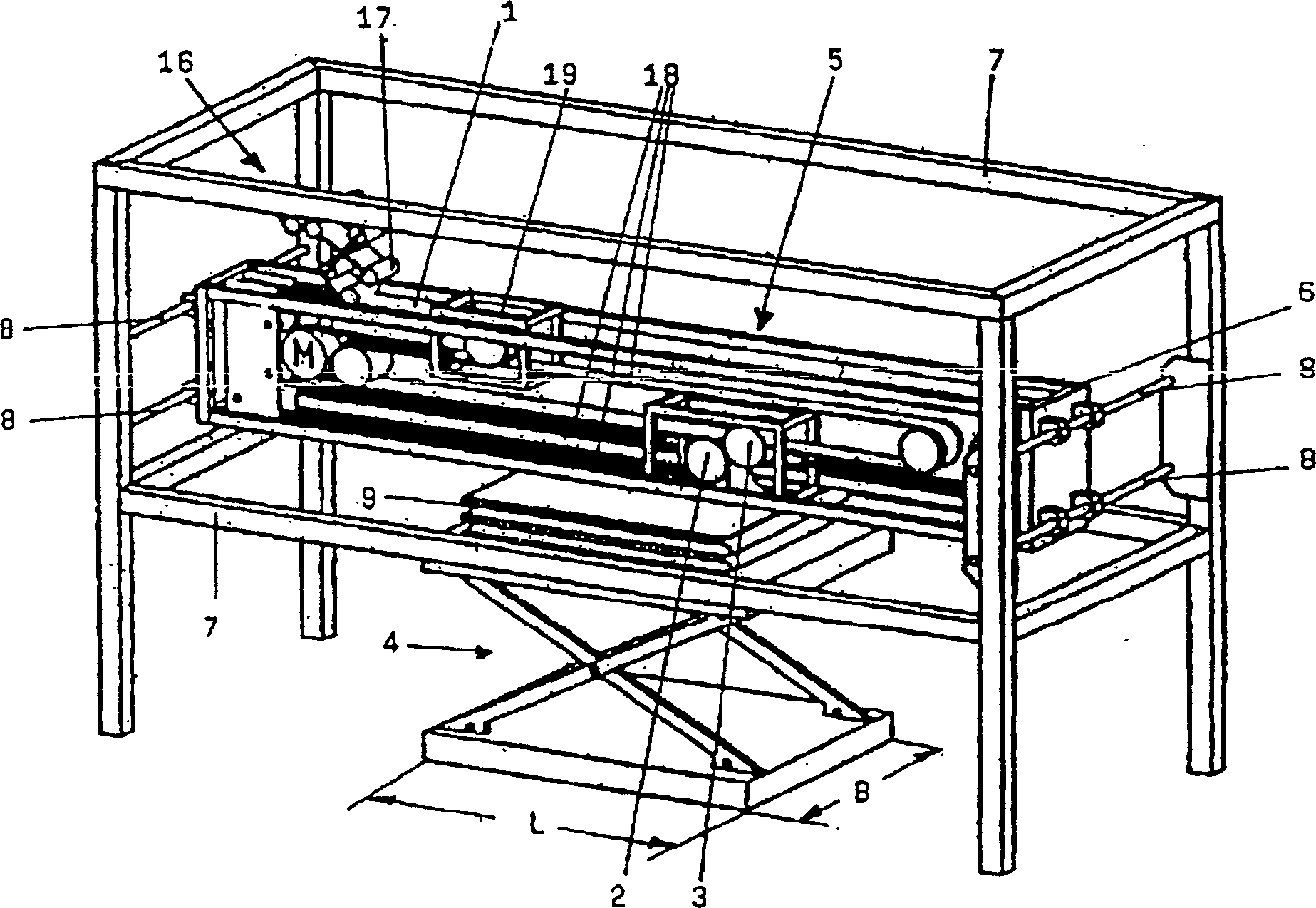
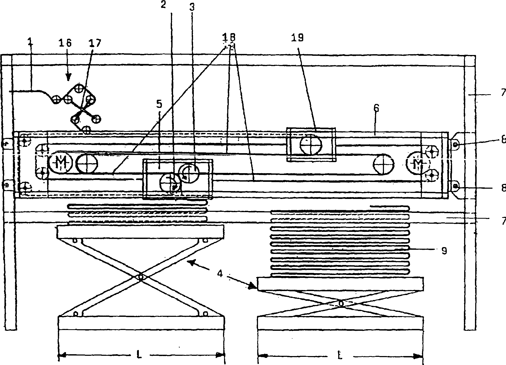
[0030] Figures 1 to 7 Denotes a device with at least one pair of counter-rotating stacking rollers 2, 3 for stacking a flexible material strip 1, wherein the material strip 1 can be transported to at least one stacking location 4 by means of the stacking rollers 2, 3, where the stacking roller 2 and 3 are a part of stacking dolly 5, which can travel by reversible orientation at least on the stacking length L of material strip 1.

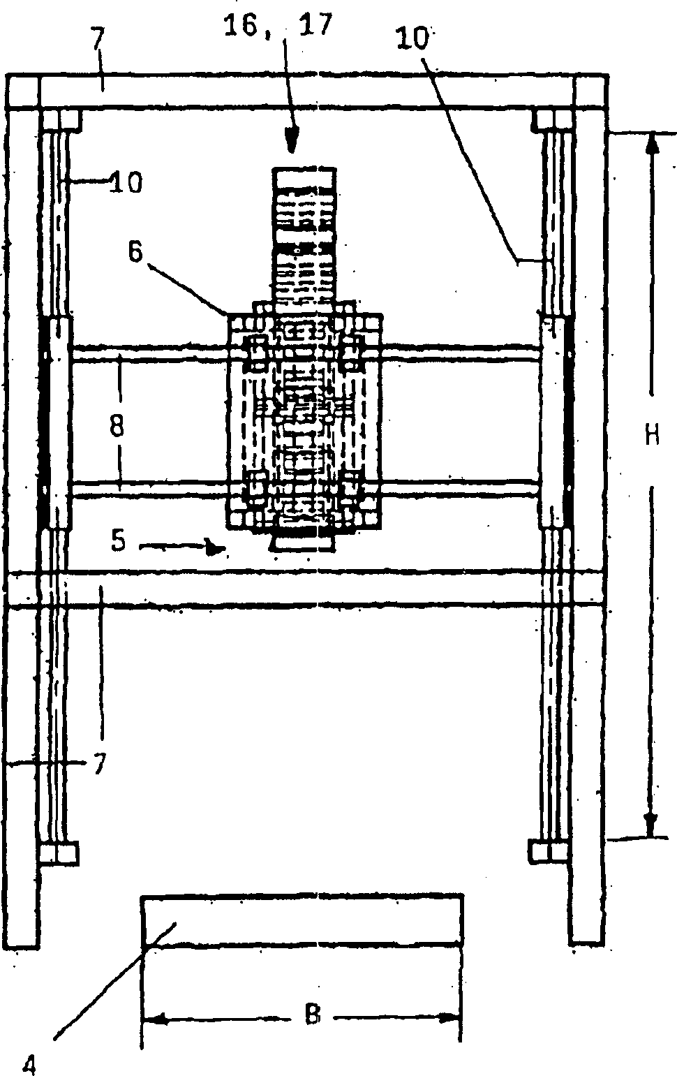
[0031] According to the present invention, the stacking trolley 5 has a smaller width than the stacking location 4 and can travel reversibly on the stacking width B of the stacking location 4 . For this reason, the stacking trolley 5 is an integral part of a frame 6 mounted on the frame 7 in a laterally movable manner. The machine frame 7 has on its end faces transversely extending guide beams 8 on which the frame 6 is displaceably mounted.

[0032] exist figure 1 A first embodiment is represented in the middle, wherein the stacking position 4 is...


PUM


Abstract

A device for laying a flexible material web 1 on a point of deposit 4 and which has at least one pair of deposit rollers 2, 3 that rotate in opposite directions. The deposit rollers 2, 3 form part of a deposit carriage 5 which is reciprocated in a reversible direction over at least the deposit length L of the material web 1. The device is more cost-effective in that the deposit carriage 5 has a smaller width than the point of deposit 4 and is reciprocated in a reversible direction over at least the deposit width B of the point of deposit 4.

Description

technical field [0001] The invention relates to a flexible material strip stacking device, which has at least one pair of counter-rotating stacking rollers, wherein the material strip can be conveyed to at least one stacking position by means of the stacking rollers, and the stacking roller is a part of the stacking trolley, which at least It can run in a reversible orientation on the stacked length. Background technique [0002] A device of the stated type is known from DE 101 25 452 C2, in which the material web is fed to the depositing station via depositing rollers. The stacking roller is an integral part of the stacking trolley, and it has a width dimension equivalent to the width of the stacking part. The stacking parts can be designed as pallets, lifting tables, cardboard boxes and so on. A stacking position is set for each stacking trolley, which can be stacked on it along the vertical and horizontal directions. The stacking along the longitudinal direction is rea...

Claims


Application Information

Patent Timeline
Patent Type & Authority Applications(China)
IPC IPC(8): B65H45/105
CPCB65H45/105
Inventor P·施泰厄
Owner SAURER GMBH & CO KG
Why Eureka
Try Eureka