Main girder of single-girder crane

A crane and single girder technology, applied in the direction of load hanging components, transportation and packaging, supporting structure, etc., can solve the problem of poor welding conditions of the internal ribs of the box-shaped main girder, large width of the box-shaped steel plate of the main girder, and steel plate forming process Trouble and other problems, to save the length of the weld, reduce the weight of the main beam, improve the effect of welding efficiency

Inactive Publication Date: 2012-06-27
王松江
View PDF15 Cites 9 Cited by
  • Summary
  • Abstract
  • Description
  • Claims
  • Application Information

AI Technical Summary

Problems solved by technology

Through the method of cold-bending the steel plate, although the welding seam of the main girder of the crane can be reduced to two and the camber problem of the main girder is solved, the following problems are found in the structure during the manufacturing process: 1. When the main girder is cold The height after bending is too large, for example, when the height exceeds 700mm, the welding conditions of the internal ribs of the box girder are poor
2. The steel plate forming process of the box-type main girder is relatively cumbersome. When using presses and bendi

Method used


Image

  • Main girder of single-girder crane
  • Main girder of single-girder crane
  • Main girder of single-girder crane

Examples


Embodiment 1

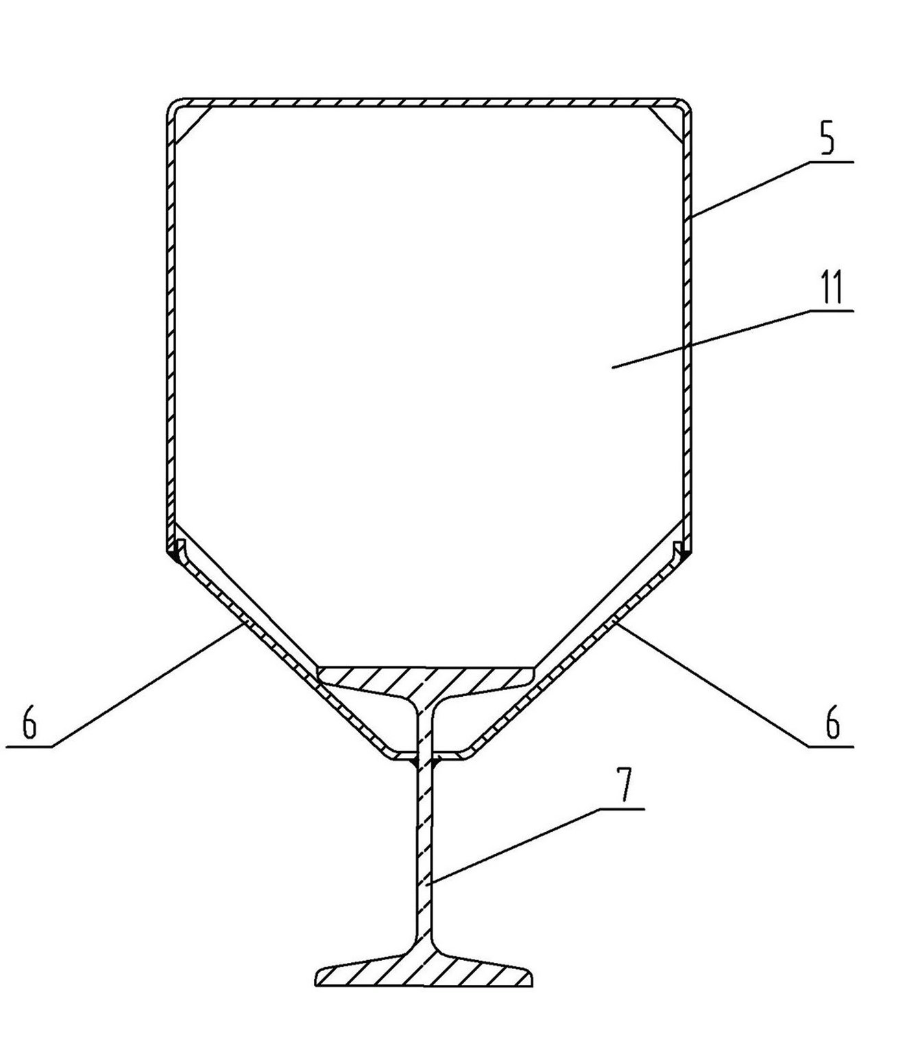
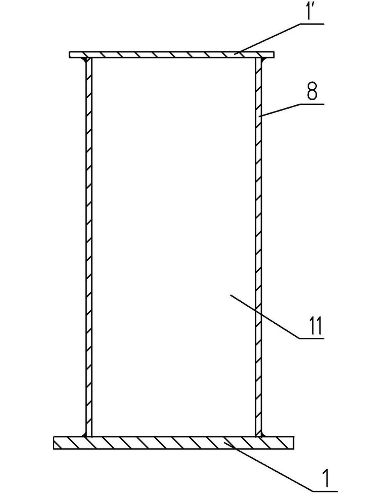
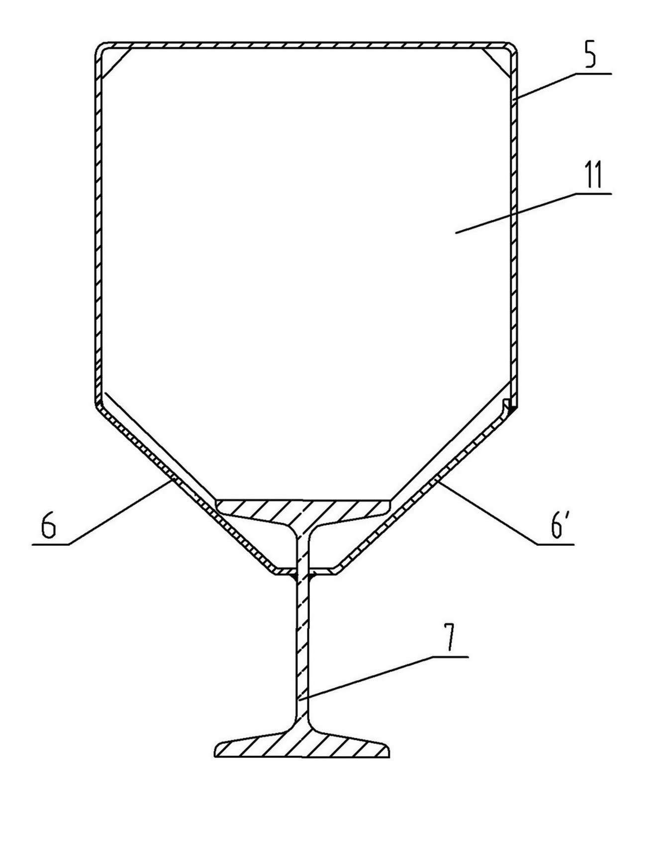
[0043] see Figure 5 , Figure 6 , in the figure, the girder of the single-girder crane of the present invention includes an upper load-bearing plate 16, a lower load-bearing plate 1″, and two symmetrical special-shaped sides that weld the upper load-bearing plate 16 and the lower load-bearing plate 1″ together. Plates 17, 17', reinforcement plates 11 are fixed at intervals along the transverse direction in the inner cavity of the beam main body, the cross section of the main beam is an approximate composite section, the upper part is a lower opening rectangle 9', and the middle is an upper and lower opening inverted, etc. Waist trapezoidal 9 ", the bottom is an upper opening rectangle 10 ', and the long sides and wide sides of the upper lower opening rectangle 9 ' are greater than the long sides and wide sides of the lower upper opening rectangle 10 ', and the width of the upper bearing plate 16 is greater than two The maximum width between the side plates 17, 17', the width...

Embodiment 2

[0049] see Figure 7 to Figure 9 , in the figure, the meanings of the same numbers in this embodiment and the first embodiment are the same and will not be repeated. The difference is that there is also a strip-shaped transition steel plate 13 between the upper load-bearing plate 16 and the reinforcing plate 11 in this embodiment. , the transitional steel plate 13 is welded on the upper end surface of the reinforcement plate 11, and the corresponding position of the transitional steel plate 13 and the upper load-bearing plate 16 is horizontally provided with a slender rectangular through-hole 14, through which the transitional steel plate 13 and the upper load-bearing plate 16 are connected from the outside. welded together; the length of the transition steel plate 13 is slightly smaller than the width of the reinforcing plate 11, the length of the through hole 14 is slightly shorter than the length of the transition steel plate 13, and the width of the through hole 14 is small...

Embodiment 3

[0053] see Figure 10 The meanings of the same numbered parts in this embodiment and the second embodiment are the same and will not be repeated. The difference is that the reinforcing plate 11 in this embodiment is provided with a through hole 15 with a flange.


PUM


Abstract

The invention relates to an improved structure of a main girder of a crane and especially to a main girder of a single-girder crane. The main girder comprises an upper bearing plate, a lower bearing plate and two symmetrical special-shaped side plates; reinforcing plates are fixed in an inner cavity of a main girder body along a transverse direction at intervals; the cross section of the main girder is an approximate combined section, the upper part of the section is a rectangle with a bottom opening, the middle part of the section is a reversed isosceles trapezoid with a top opening and a bottom opening, the lower part of the section is a rectangle with a top opening, and the length and the width of the rectangle with a bottom opening at the upper part are respectively greater than the length and the width of the rectangle with a top opening at the lower part; the width of the upper bearing plate is greater than the maximum width between the two side plates, the width of the lower bearing plate is greater than the minimum width between the two side plates but smaller than the maximum width between the two side plates, the thickness of the upper bearing plate is greater than or equal to the thickness of the two side plates, and the thickness of the lower bearing plate is greater than the thickness of the two side plates. The main girder provided in the invention has a simple structure, is easy to manufacture and process, enables manufacture cost to be reduced and production efficiency to be improved and is especially applicable to flow line production; in the process of manufacturing the main girder, the problem of camber of the main girder of a crane is easily overcome, and the service life of the crane is prolonged, so the main girder can be easily popularized and applied.

Description

technical field [0001] The invention relates to an improved structure of a main girder of a crane, in particular to a main girder of a single girder crane. Background technique [0002] At present, there are generally two main girder structures of electric single-girder cranes and hoist gantry cranes (such as figure 1 , figure 2 As shown), one is to use the steel plate to roll into a U-shaped groove, weld the supporting ribs in the U-shaped groove, then weld the I-beam and the ribs, and finally weld the I-beam and the U-shaped groove together with the side plate , the production method has more butt welds; both the U-shaped groove and the side plate need to be cold-formed or calendered. Since the main beam requires a certain degree of camber according to the current national standard, the U-shaped groove must be formed during the tailor-welded combination For a certain camber, the I-beam also needs to be formed by cold bending or flame heating; and because of the position...

Claims


Application Information

Patent Timeline
IPC IPC(8): B66C6/00
Inventor 王松江
Owner 王松江
Why Eureka
Try Eureka