Cylindrical permanent magnet linear motor with high thrust density

A permanent magnet linear motor, cylindrical technology, applied in electrical components, electromechanical devices, propulsion systems, etc., can solve problems such as poor overload capacity and low thrust density, reduce processing difficulty and assembly clearance, and improve thrust density. , Improve the effect of magnetic density

Active Publication Date: 2010-08-04
HARBIN INST OF TECH
View PDF5 Cites 18 Cited by
  • Summary
  • Abstract
  • Description
  • Claims
  • Application Information

AI Technical Summary

Problems solved by technology

[0003] The purpose of the present invention is to provide a high thrust density cylindrical permanent magnet linea

Method used


Image

  • Cylindrical permanent magnet linear motor with high thrust density
  • Cylindrical permanent magnet linear motor with high thrust density
  • Cylindrical permanent magnet linear motor with high thrust density

Examples


specific Embodiment approach 1

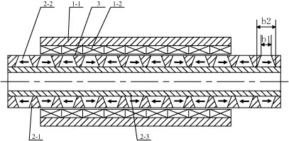
[0009] Specific implementation mode one: the following combination figure 1 and figure 2 Describe this embodiment, this embodiment includes a primary and a secondary, the primary is composed of an armature core 1-1 and an armature winding 1-2, the armature core 1-1 is cylindrical and made of a magnetically conductive material, the armature The iron core 1-1 is radially provided with a first through slot 1-1-1, the center line of the first through slot 1-1-1 is parallel to the axial direction of the motor, and the armature winding 1-2 is assembled on the armature core On the inner wall of 1-1, the armature winding 1-2 is composed of multiple pie-shaped windings arranged in a cylindrical shape in phase sequence, each pie-shaped winding is an independent winding, and the terminals of the multiple pie-shaped windings pass through the The first through slots 1-1-1 are connected to each other; there is an air gap 3 between the inner circular surface of the armature winding 1-2 an...

specific Embodiment approach 2

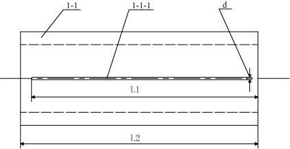
[0012] Specific implementation mode two: the following combination figure 1 and figure 2 This embodiment is described. The difference between this embodiment and Embodiment 1 is that the armature core 1-1 has a second through slot in the radial direction, and the center line of the second through slot is parallel to the axial direction of the motor. The size of the second through slot is equal to that of the first through slot 1-1-1 and they are oppositely arranged. The axial length L1 of the first through slot 1-1-1 is smaller than the axial length L2 of the armature core 1-1, so The terminals of the plurality of pie-shaped windings respectively pass through the first through slot 1-1-1 and the second through slot and are connected. Other components and connections are the same as those in Embodiment 1.

[0013] On the armature iron core 1-1, the first through groove 1-1-1 can be opened as required, and the first through groove 1-1-1 and the second through groove 1-1-1 ca...

specific Embodiment approach 3

[0015] Specific implementation mode three: combination figure 1 Describe this embodiment, this embodiment is a further description of Embodiment 1 or 2. In this embodiment, the surface where the long side of the isosceles trapezoidal section of the permanent magnet 2-2 is located is the inner ring surface of the permanent magnet 2-2. Other compositions and connections are the same as those in the first or second embodiment.

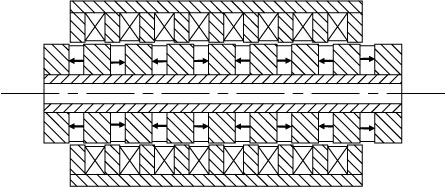
[0016] The inner ring surface of the permanent magnet 2-2 where the long side of the isosceles trapezoid is located matches the outer circular surface of the non-magnetic shaft tube 2-3, and the outer ring surface of the permanent magnet 2-2 where the short side of the isosceles trapezoid is located An air gap 3 is formed with the inner circular surface of the armature winding 1-2. A plurality of secondary iron cores 2-1 are respectively arranged between two adjacent permanent magnets 2-2, and the shape of the secondary iron cores 2-1 matches the perman...


PUM


Abstract

The invention relates to a cylindrical permanent magnet linear motor with high thrust density, belonging to the technical field of motors and solving the problems of low thrust density and poor overload capability of traditional cylindrical motors. The primary of the cylindrical permanent magnet linear motor with high thrust density comprises an armature iron core and an armature winding, wherein the armature iron core is radially provided with a first channel, the central line of the first channel is parallel to the axial direction of the motor, the armature winding is assembled on the inner wall of the armature iron core and comprises a plurality of cake-shaped windings which are arranged in a cylinder shape according to a phase sequence, the wiring terminals of the cake-shaped windings respectively penetrate through the first channel and are connected, and an air gap is formed between the inner circumferential surface and the secondary outer surface of the armature winding. A plurality of secondary iron cores and a plurality of permanent magnets are mutually separated and sleeved in match on the outer circumferential surface of a non-magnetic beam barrel, two secondary iron cores are respectively sleeved at two end parts on the outer circumferential surface of the non-magnetic beam barrel, the axial cross section of each permanent magnet is an isosceles trapezoid, each permanent magnet is in an axial magnetism-charging structure, and the adjacent permanent magnets have opposite magnetism-charging directions. The invention is used as a linear motor.

Description

technical field [0001] The invention relates to a high thrust density cylindrical permanent magnet linear motor, which belongs to the technical field of motors. Background technique [0002] Cylindrical linear motors have high practical value in linear motion applications due to their advantages of high winding utilization, no lateral end windings, and no unilateral magnetic pull. The existing cylindrical linear motor has a structure such as image 3 As shown, its armature core adopts a cogged structure, and the pie-shaped winding is embedded in the core slot. The defect of this form is that the processing and assembly of the motor are difficult on the one hand; on the other hand, when the motor drives the load, The armature reaction can easily cause the magnetic density saturation of the tooth core, resulting in the distortion of the air gap magnetic field, resulting in the increase of the thrust fluctuation of the motor, the decrease of the average thrust and the increase ...

Claims


Application Information

Patent Timeline
IPC IPC(8): H02K41/02
Inventor 李立毅黄旭珍曹继伟潘东华
Owner HARBIN INST OF TECH
Why Eureka
Try Eureka