

Washing machine
A technology of a washing machine and a driving mechanism, applied in the field of washing machines, which can solve the problems of energy consumption, water consumption, wasting a lot of time, and excessive water consumption, and achieve the effects of simple and light structure, clean laundry, and energy saving
- Summary
- Abstract
- Description
- Claims
- Application Information
AI Technical Summary
Problems solved by technology
Method used
Image

Examples
Embodiment 1
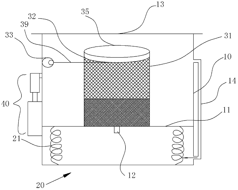
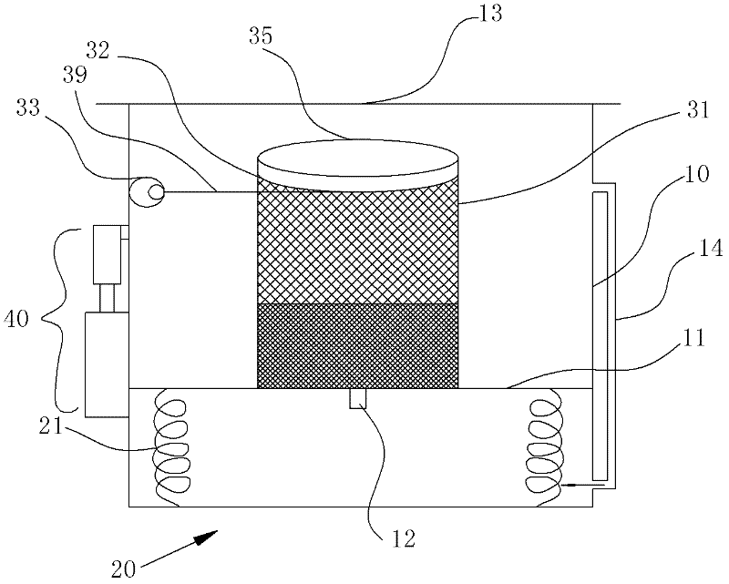
[0010] Such as figure 1 As shown: the lower part of the piston plate 11 is connected to one end of the spring 21, and the other end of the spring 21 is connected to the bottom of the barrel; the washing machine also includes a net pocket 31, and the net pocket 31 is located in the barrel cavity above the piston plate 11 , the bottom of the net pocket 31 is connected to the piston plate 11, the opening of the net pocket 31 is upward, and a ring 32 is arranged on the edge of the opening of the net pocket 31, and the ring 32 realizes the net pocket 31 under the action of the second driving mechanism. The open end makes reciprocating twisting motion in the horizontal plane. The specific working state is: the clothes are placed inside the net bag 31, and a cover 35 is added on the ring 32 of the upper open end to prevent the clothes from running out of position when washing, and the net bag 31 open end automatically pushes the piston plate 11 of the bottom when twisting. At the sa...
Embodiment 2
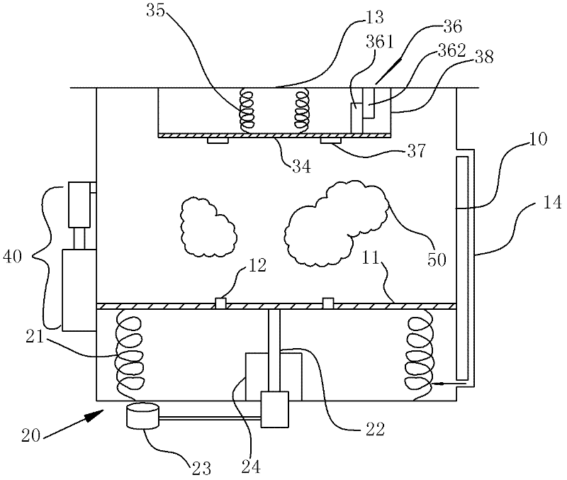
[0014] Such as figure 2 As shown: the first driving mechanism 20 includes a hydraulic device, and the hydraulic device includes a hydraulic jack 22, one end of the hydraulic jack 22 is connected to the piston plate 11, and the other end is connected to the piston in the oil cylinder , the oil cylinder is connected with the hydraulic pipeline 23; the washing machine also includes an inner plate 34, the inner plate 34 is arranged along the horizontal direction, a spring 35 is connected between the inner plate 34 and the lid portion 13, and the inner plate 34 is provided with There is an electromagnetic unit 36 that drives it to do reciprocating torsion in the horizontal plane. The electromagnetic unit 36 constitutes a second drive mechanism. The electromagnetic unit 36 includes a ferromagnetic material suction block 361 and a coil 362. The ferromagnetic material suction The block 361 is connected to the inner board 34, and the coil 362 is connected to the power supply. T...
PUM
 Abstract
Description
Claims
Application Information