Systems and methods for supporting tanks in a cargo ship

a technology for supporting tanks and cargo ships, applied in the direction of hull reinforcements, floating buildings, containers, etc., can solve the problems of limited diameter and length of such tanks, limited number of support points, and interaction between tanks and hulls, so as to reduce friction between pedestals

Active Publication Date: 2012-08-21
SSRC TECH AS
View PDF14 Cites 7 Cited by
  • Summary
  • Abstract
  • Description
  • Claims
  • Application Information

AI Technical Summary

Benefits of technology

[0012]There are disclosed systems and methods for supporting cargo tanks within the hold of a liquefied gas carrier by establishing a series of spaced-apart pedestals along the longitudinal axis of a tank, said pedestals positioned in conjunction with the ship's structural components. These pedestals are of wood or other suitable thermal insulating and load bearing material fixed to the tank below its circumferential diameter along both the starboard and port tank sides. The pedestals rest on structural longitudinal stringers laying port and starboard in the horizontal plane and fixed and supported by the ship's hull structure. Longitudinal and transverse pedestal movement is controlled by stops attached to the stringers at one or more of the pedestals. The stops contact the pedestals via bearing pads which constrain the pedestal in one direction but permit its movement in another. The bearing pads reduce the friction between pedestal and stop thereby allowing free movement in the desired direction.
[0013]In this manner, cylindrical cargo tanks having the weight and material thickness advantages of Type B cargo tanks plus the fabrication advantages of cylindrical Type C tanks can provide better utilization of the cargo space than spherical tanks and reduced material and fabrication cost of prismatic or Type C tanks. Additionally, the spaced-apart pedestals promote even distribution of loads from the tank or tanks into the ship's hull structure thereby enabling a simpler and lighter hull structure while also eliminating excessive hull deflections and reducing sensitivity due to sloshing loads. The design of the pedestals, stops and bearing pads minimize thermal heat transfer and allow for normal cargo tank and hull deflections without adverse affects. Single tank capacities of 15,000 m3 or more may be realized with the concepts discussed herein.

Problems solved by technology

The diameter and length of such tanks are limited by technical and economic constraints such that the largest single tank known to have been constructed to date has a capacity of about 6,000 m3 and the largest ship capacity is believed to be approximately 12,000 m3.
The interaction between tank and hull due to deformation of each is complex and limits the number of support points to two.
The diameter of such tanks is practically limited by the density of the cargo, the design pressure of the tank, saddle spacing, fabrication restrictions and economic factors.
The limitation of two support saddles for each tank results in very large, highly concentrated loads being imposed on the ship's bottom structure.
Such hulls are difficult to fabricate and require more steel than a hull where the cargo load is evenly distributed along the ship's length.
However, due to the dynamic loads such tanks are subjected to at sea, the IGC Code requires liquefied gas carrier tanks to be designed to increased design pressures, acceleration forces and safety factors as compared to land-based tanks.
This results in large shell material thickness, high tank weight and excessive cost.
Since most liquefied gases are carried at atmospheric pressure, the Type C tank is a disadvantage in weight and cost.
Determining the actual expected design loads is a time consuming and expensive process, but such tanks may be designed with lower material thickness and weight compared to a Type C tank.
However, spherical tanks are expensive to fabricate and are generally used only in large liquefied natural gas (LNG) carriers.
In addition to the cost disadvantage, spherical tanks do not utilize the available space in the ship's cargo hold as well as cylindrical tanks and therefore a larger ship must be designed to obtain the same transport capacity.
The surrounding ship's hull structure must therefore be constructed of expensive, low temperature steel which remains tough and crack resistant at the boiling temperature of the liquefied gas (usually LPG, propane or ammonia).
Although prismatic tanks have a better volumetric efficiency in the hull than do cylindrical or spherical tanks, they require considerably more material and have limited design pressure.

Method used


Image

  • Systems and methods for supporting tanks in a cargo ship
  • Systems and methods for supporting tanks in a cargo ship
  • Systems and methods for supporting tanks in a cargo ship

Examples


Embodiment Construction

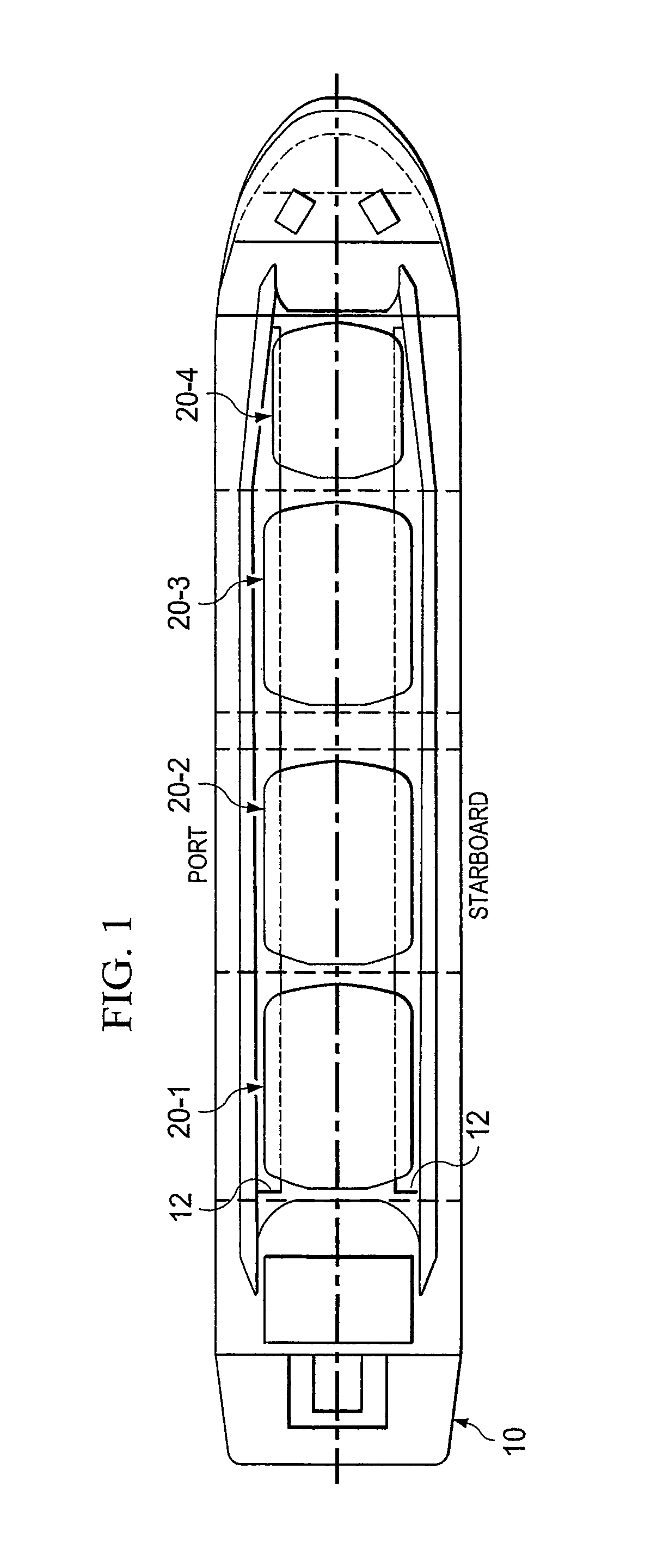
[0023]FIG. 1 shows a top view of liquefied gas carrier 10, having cargo tanks 20-1 though 20-4 arranged therein. Note that while the cargo tanks are shown in a straight line displaced along the longitudinal axis of the ship, the concepts discussed herein can be used with any placement of tanks and with any number of tanks.

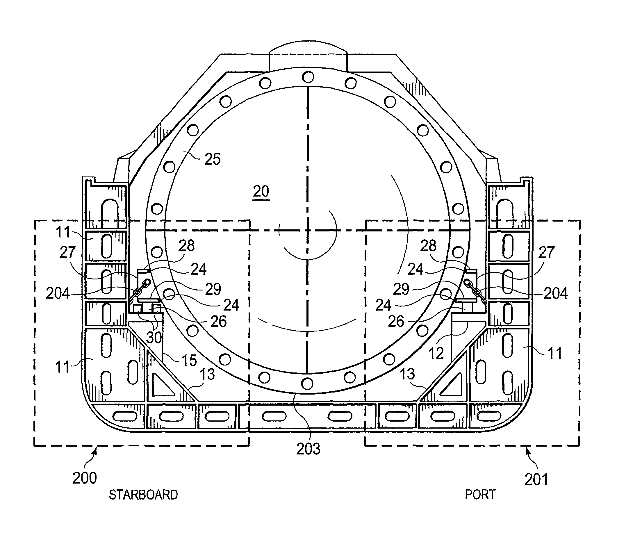
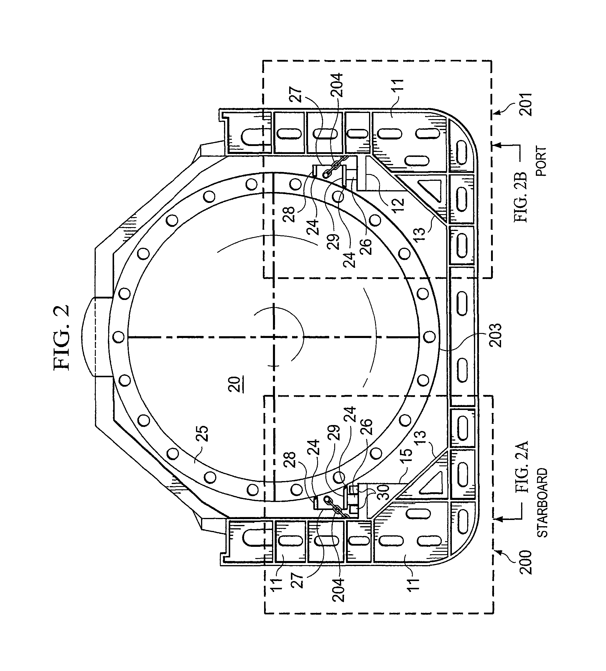
[0024]FIG. 2 shows a cross-section of tank 20 being supported by the system and method described herein. In order to facilitate the support system of this invention it is advantageous to add a support structure, such as the longitudinal stringer 12 which is integrated into the ship's hull structure comprised of transverse web frames 11 and longitudinal bulkheads 13 or girders 14, as shown in FIGS. 2A and 2B. Note that while structures 12, 13 and 14 are preferably continuous structures they can be discontinuous and placed only where necessary.

[0025]Before discussing the inventive concepts of this invention it might be helpful to review a prior art support structure ...


PUM


Abstract

There are disclosed systems and methods for supporting cargo tanks within the hold of a liquefied gas carrier by establishing a series of spaced-apart pedestals along the longitudinal axis of a tank, said pedestals positioned in conjunction with the ship's structural components. These pedestals are of wood or other suitable thermal insulating and load bearing material fixed to the tank below its circumferential diameter along both the starboard and port tank sides. The pedestals rest on structural longitudinal stringers laying port and starboard in the horizontal plane and fixed and supported by the ship's hull structure. Longitudinal and transverse pedestal movement is controlled by stops attached to the stringers at one or more of the pedestals. The stops contact the pedestals via bearing pads which constrain the pedestal in one direction but permit its movement in another.

Description

CROSS-REFERENCE TO RELATED APPLICATIONS[0001]This application claims priority to Provisional Patent Application Ser. No. 61 / 129,639 filed Jul. 9, 2008 entitled SUPPORT SYSTEM FOR CYLINDRICAL CARGO TANKS CONTAINING LIQUEFIED BULK GAS IN MARINE APPLICATIONS, which application is hereby incorporated by reference herein.TECHNICAL FIELD[0002]This disclosure relates generally to a support system for independent cargo tanks containing liquefied gases and is particularly useful in enabling large diameter cryogenic tanks to be safely installed and operated on liquefied gas carriers.BACKGROUND OF THE INVENTION[0003]It is now common to transport liquefied gases and other materials in tanks positioned within the holds of cargo ships. Particularly, it is well known that liquefied gases, such as LPG, ethylene and LNG, can be transported in tanks permanently attached within the holds of a cargo ship.[0004]The design and construction of liquefied gas carriers is regulated by the International Marit...

Claims


Application Information

Patent Timeline
Patent Type & Authority Patents(United States)
IPC IPC(8): B63B25/12B65D90/12B63B17/00B63B3/70F17C13/08B63B25/14B63B25/16
CPCB63B3/70B63B17/0081B63B25/16B63B25/14B63B25/12
Inventor HOLLAND, JOHN RANDOLPHFICHELMANN, WOLFGANGWOLLERT, JUERGEN
Owner SSRC TECH AS
Why Eureka
Try Eureka