
Server

A server and connector technology, applied in the server field, can solve the problems of not being able to provide larger bandwidth, unstable information transmission, etc., and achieve the effect of improving stability, improving computing power, and transmitting large-bandwidth signals

Inactive Publication Date: 2012-06-27
SUGON INFORMATION IND
View PDF3 Cites 8 Cited by
  • Summary
  • Abstract
  • Description
  • Claims
  • Application Information

AI Technical Summary

Benefits of technology

This patented technology allows for better utilization of computer resources while still maintaining stable operation. It achieves this with multiple central processing units (CPU) placed next to each other within one chassis called the main system's chip card unit that connect it directly onto another chipcard without any intervening wires connecting them together. These connections ensure consistently good signal quality even at very fast speeds.

Problems solved by technology

Technological Problem: Current methods require that each computer has its own dedicated hardware platform or requires multiple computers with different types of connections. Additionally, current systems are slow because they rely heavily upon signal transmission speeds over communication busses due to their limitations in terms of processing capabilities and data exchange rates.

Method used


Image

  • Server
  • Server
  • Server

Examples


Embodiment Construction

[0024] The preferred embodiments of the present invention will be described below with reference to the accompanying drawings. It should be understood that the preferred embodiments described here are only used to illustrate and explain the present invention, and are not used to limit the present invention.

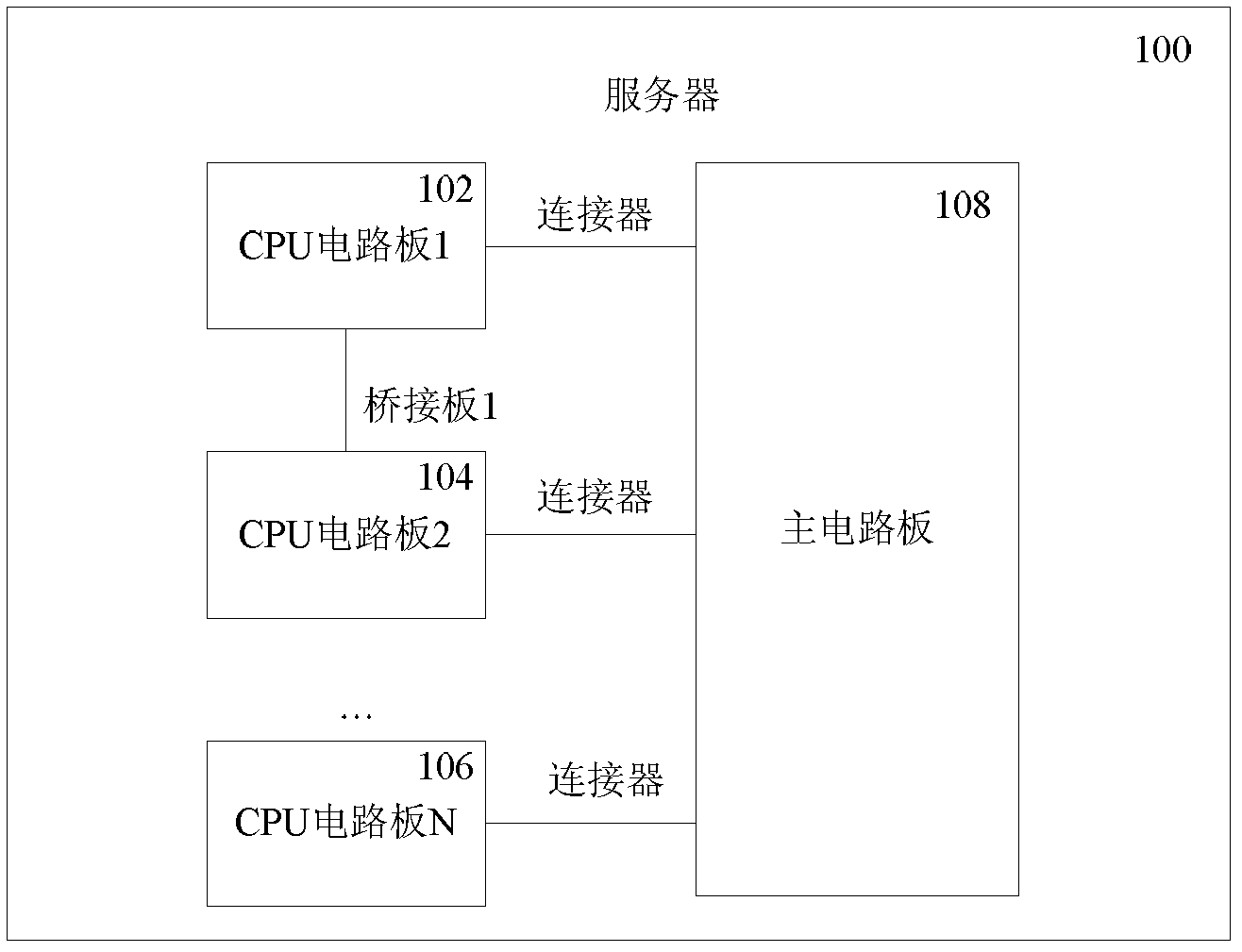
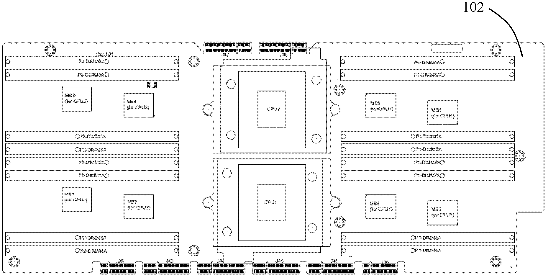
[0025] figure 1 It is a diagram of the overall structure of a server according to an embodiment of the present invention. The server 100 includes: a main circuit board 108; multiple CPU circuit boards, a CPU circuit board 1102, a CPU circuit board 2104, and a CPU circuit board N 106. Each CPU circuit board is provided with at least one CPU and both sides are provided with useful A connector for electrical connection; and a plurality of bridge boards, wherein each CPU circuit board is electrically connected to one of the main circuit board 108 and the bridge board through a connector.

[0026] Through the embodiment of the present invention, multiple CPUs can be arranged on the...


PUM


Abstract

The invention provides a server, which comprises a main circuit board, a plurality of CPU (central processing unit) circuit boards and a plurality of bridging plates. At least one CPU is arranged on each CPU circuit board, connectors used for being electrically connected are disposed on two sides of each CPU circuit board, and each CPU circuit board is electrically connected with one of the main circuit boards and the bridging plates by the connectors. More CPUs can be arranged on the main circuit board by the CPU circuit boards to improve computation capacity of the server, interconnection architecture among the CPU circuit boards, the CPU bridging plates and the main circuit board is realized, accordingly, information transmission among the CPUs and the main circuit board is realized, and stability of the server is enhanced.

Description


Claims


Application Information

Patent Timeline
Owner SUGON INFORMATION IND
Learn More