Movable inclined platform type automatic steel bar bending machine

A bending machine and inclined table technology, applied in the field of mobile inclined steel bar automatic bending machines, can solve the problems of excessively large shape of the steel bar automatic bending machine, the limitation of the minimum bending size, and the complicated machine operation process, so as to overcome the bending operation and operation. The effect of easy, user-friendly operation

Active Publication Date: 2012-07-04
TJK MACHINERY TIANJIN
View PDF7 Cites 7 Cited by
  • Summary
  • Abstract
  • Description
  • Claims
  • Application Information

AI Technical Summary

Problems solved by technology

[0006] 1. Since the height of the unloading frame is consistent with that of the automatic steel bar bending machine, when the steel bar is manually placed on the horizontal workbench of the steel bar automatic bending machine, the height of the bending axis and the central axis is higher than the horizontal workbench of the steel bar automatic bending machine. The steel bar needs to be lifted beyond the height of the bending axis and the central axis before being placed between the bending axis and the central axis; there is a defect that the operation is inconvenient and the operator is easy to be injured
[0007] 2. Although the existing planar automatic steel bar bending machine can bend in both directions, the minimum size of the bending is limited due to the excessive size of the automatic steel bar bending machine
[0008] 3. The prior art planar steel bar automatic bending machine includes a fixed bending machine and a mobile bending machine. The bending process takes a long time, the production efficiency is low, and the machine operation process is complicated; labor-intensive

Method used


Image

  • Movable inclined platform type automatic steel bar bending machine
  • Movable inclined platform type automatic steel bar bending machine
  • Movable inclined platform type automatic steel bar bending machine

Examples


Embodiment Construction

[0019] Embodiments of the present invention will be further described below in conjunction with the accompanying drawings.

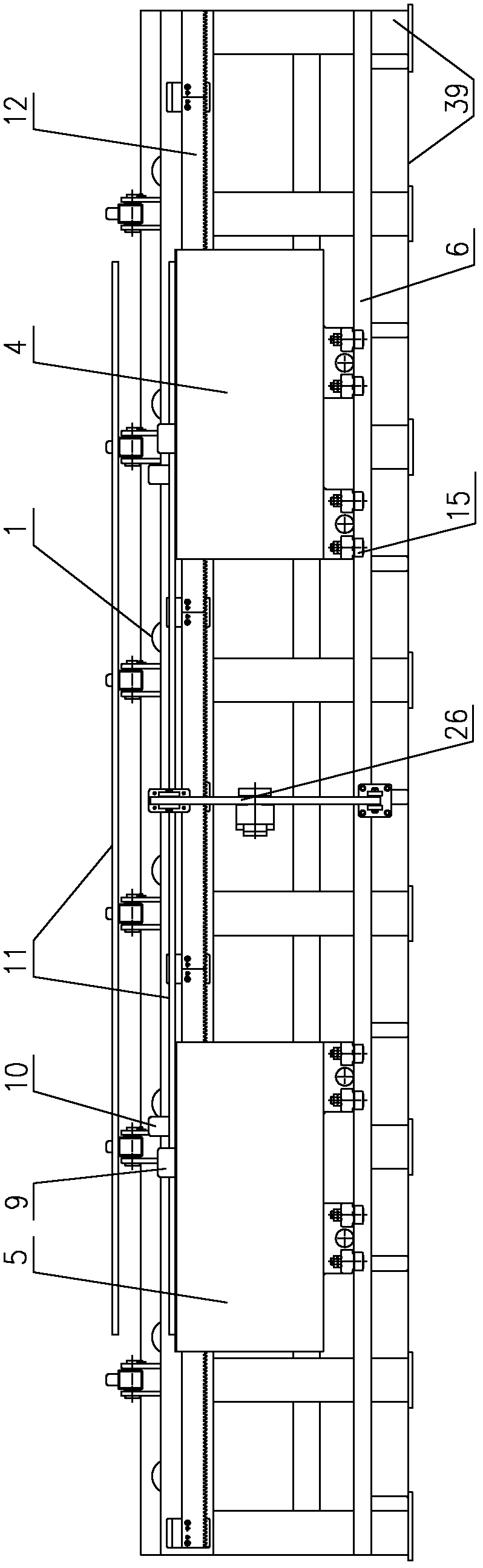
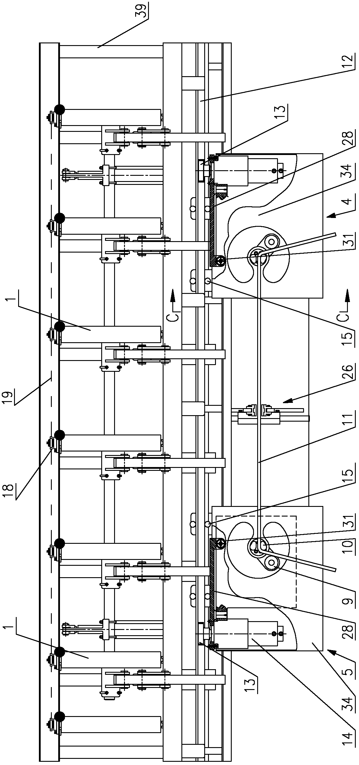
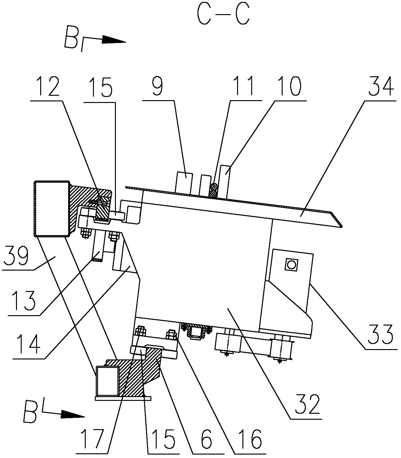
[0020] figure 1 is the front view of the present invention; figure 2 Yes figure 1 top view of image 3 Yes figure 1 Middle C-C sectional view; Figure 4 Yes image 3 Middle B-B sectional view.

[0021] As shown in the figure, the present invention provides a mobile inclined table type steel bar automatic bending machine, which includes: a frame 39; a track 6 and a rack 12 arranged on the frame 39; The first steel bar automatic bending machine 4 and the second steel bar automatic bending machine 5 that move with rack 12.

[0022] The first automatic steel bar bending machine 4 and the second steel bar automatic bending machine 5 are respectively provided with a gear transmission mechanism and a gear floating mechanism that move along the rack 12 .

[0023] The gear floating mechanism includes: a motor connection plate 28 and a support shaft 29; t...


PUM


Abstract

The invention discloses a movable inclined platform type automatic steel bar bending machine, comprising a rack, a track, a gear rack and two automatic steel bar bending machines. The two steel bar bending machines are respectively provided with a gear transmission mechanism and a gear floating mechanism which move along the gear rack; the gear floating mechanism comprises a motor connecting plate and a support shaft; the motor connecting plate penetrates through and is hinged at one end of the support shaft, and the other end of the support shaft is fixed on a cabinet of each automatic steel bar bending machine; one end of the motor connecting plate is fixed on a motor flange plate in the gear transmission mechanism, and a gear in the gear transmission mechanism is meshed with the gear rack; and the other end of the motor connecting plate is supported on the cabinet of the automatic steel bar bending machine in a floating manner. The movable inclined platform type automatic steel bar bending machine has the beneficial effects that the accurate meshing between the gear and the gear rack in a travelling mechanism of the automatic steel bar bending machine can be ensured, the running is stable, the structure is simple, and an inclined platform type working table surface saves effort, is easy to operate, ensures the safety of an operator and realizes the humanized operation.

Description

technical field [0001] The invention relates to an automatic steel bar bending machine, in particular to a mobile inclined platform automatic steel bar bending machine. Background technique [0002] The automatic steel bar bending machine is a device that bends steel bars into squares, rectangles, triangles and other shapes. The automatic steel bar bending machine in the prior art has a planar structure, and a steel bar conveying device for conveying steel bars is arranged on one side of the steel bar automatic bending machine. The height of the steel bar conveying device is consistent with the height of the steel bar automatic bending machine. [0003] The steel bar automatic bending machine with planar structure includes: a track; a fixed bending machine fixed at one end of the track; and a mobile bending machine moving on the track. The fixed bending machine includes: a chassis; a horizontal workbench arranged on the upper part of the bending machine body; the horizontal...

Claims


Application Information

Patent Timeline
Patent Type & Authority Applications(China)
IPC IPC(8): B21F1/00
Inventor 陈振东
Owner TJK MACHINERY TIANJIN
Why Eureka
Try Eureka