Tool machine, especially handheld tool machine

A technology of hand-held machine tools and machine tools, which is applied in the direction of manufacturing tools, portable mobile devices, metal processing equipment, etc., and can solve problems such as increasing frictional resistance and affecting efficiency

Active Publication Date: 2012-07-04
ROBERT BOSCH GMBH
View PDF5 Cites 0 Cited by
  • Summary
  • Abstract
  • Description
  • Claims
  • Application Information

AI Technical Summary

Problems solved by technology

But these sealing lips slide on the rotor shaft and thus increase the frictional resistance, thus adversely affecting the efficiency

Method used


Image

  • Tool machine, especially handheld tool machine
  • Tool machine, especially handheld tool machine
  • Tool machine, especially handheld tool machine

Examples


Embodiment Construction

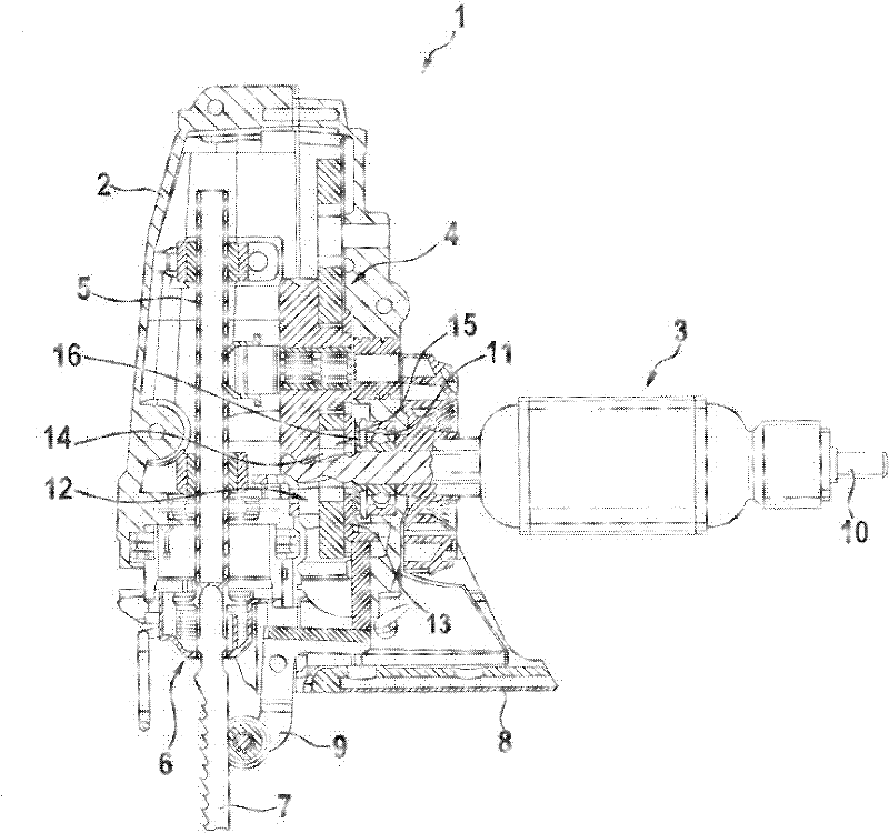
[0020] Such as figure 1 As shown, the jigsaw 1 has a housing 2 in which are arranged an electric drive motor 3 and a transmission 4 for driving a reciprocating rod 5 on which a saw blade 7 is fastened via a fastening device 6 . On the underside of the housing 2 there is a base plate 8 which bears on the upper side of the workpiece during its machining. The saw blade 7 is arranged in front of the base plate 8 , wherein if necessary a recess can also be provided in the base plate 8 through which the saw blade 7 passes. The saw blade 7 is supported on the rear by a housing-side support device 9 .

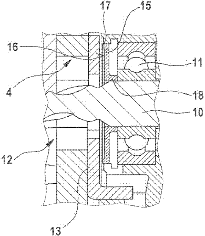
[0021] The electric drive motor 3 has a rotor shaft or armature shaft 10 , the longitudinal axis of which is oriented orthogonally to the longitudinal axis of the reciprocating rod 5 . A section of the rotor shaft 10 protruding beyond the stator of the drive motor 3 is mounted rotatably in a ball bearing 11 in the housing, the ball bearing 11 being designed as a deep groove ball bear...


PUM


Abstract

The present invention relates to a tool machine, and especially relates to a handheld tool machine, such as a barbed saw, comprising an electrical drive motor and a transmission arranged at a downstream of the drive motor and used for driving a tool. A rotor shaft of the drive motor is supported in a housing of the tool machine through a ball bearing. A sealing disc is arranged on the rotor shaft in a way of not relatively rotating, and the sealing disc is arranged between the ball bearing and a transmission component coupled to the rotor shaft.

Description

technical field [0001] The invention relates to a power tool, in particular a hand-held power tool, such as a jigsaw. Background technique [0002] A hand-held power tool such as a jigsaw has an electric drive motor in a housing, the drive movement of which is converted into a working movement of the tool via a transmission, for example a planetary transmission. In the case of a jigsaw, a reciprocating rod mounted displaceably in the housing is set in a counter-rotating up and down reciprocating movement, to which the saw blade can be coupled. [0003] The rotor shaft of the electric drive motor drives a transmission component and is mounted in the housing via ball bearings. The transmission components are lubricated by transmission grease, wherein, in order to avoid transmission of transmission grease along the rotor shaft of the motor out of the transmission chamber, an upper sealing lip is formed on the ball bearing, the sealing lip should prevent the transmission grease...

Claims


Application Information

Patent Timeline
Patent Type & Authority Applications(China)
IPC IPC(8): B23D49/16B23D51/16B25F5/00
CPCB23D51/16B25F5/001
Inventor G・普罗布斯特D・泽格塞尔
Owner ROBERT BOSCH GMBH
Why Eureka
Try Eureka