Spring clip

A spring clip and clamping block technology, applied in the field of spring clips, can solve the problems of reducing the degree of freedom, increasing the cost, and higher material requirements, and achieving the effect of reducing processing costs, low costs, and low material requirements.

Inactive Publication Date: 2012-07-04
HANGZHOU GREAT STAR IND CO LTD
View PDF11 Cites 5 Cited by
  • Summary
  • Abstract
  • Description
  • Claims
  • Application Information

AI Technical Summary

Problems solved by technology

Since a part of the L-shaped element protrudes from the main body, another hand is needed for adjustment, which reduces the degree of freedom of the hand and makes it less convenient to use
In addition, the friction surface between the rod and the L-shaped element is basically parallel to the pivot, and there are also the aforementioned problems of excessive wear and long-term use of the reliability of the locking function, and the requirements for materials are relatively high, resulting in increased costs.

Method used


Image

  • Spring clip
  • Spring clip
  • Spring clip

Examples


Embodiment 1

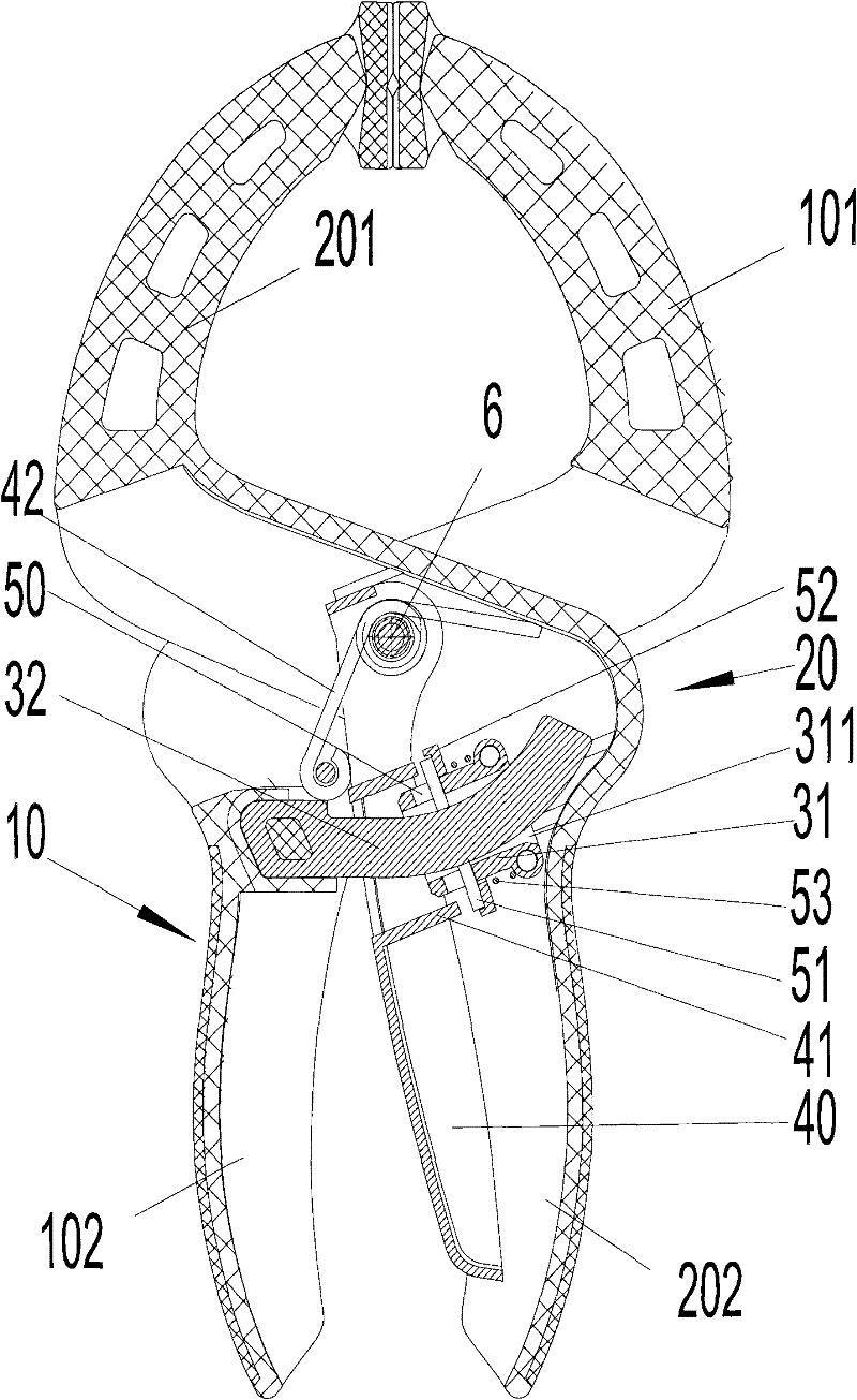
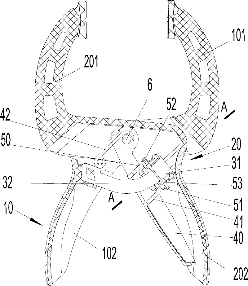
[0047] Such as figure 1 and 2 As shown, a specific embodiment of the spring clip of the present invention includes a first body 10, a second body 20, and a first pivot that pivotably couples the first body 10 and the second body 20 together 6. The first main body 10 and the second main body 20 respectively include a gripping portion 102 , 202 and a clamping portion 101 , 201 . The clamping parts of the two main bodies 10, 20 can also be respectively provided with movable chucks, so as to facilitate clamping.

[0048] The first pivot 6 is made of screws, bolts, rivets, etc., and is located in the middle of the first body 10 and the second body 20. The lower half of the first body 10 and the second body 20 can respectively form a semi-open cavity. And it can be covered with a soft covering layer on the outside, such as leather, artificial leather, plastic or rubber.

[0049] The spring clip of the present invention also includes a locking mechanism. The locking mechanism in...

Embodiment 2

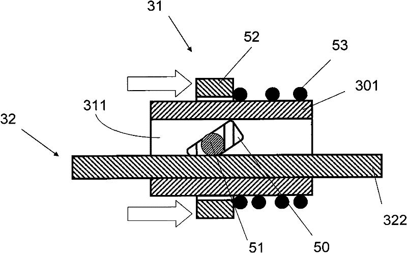
[0069] The structure of another specific embodiment of the spring clip of the present invention is similar to that of Embodiment 1, the difference lies in its locking mechanism. Such as Figure 4 As shown, two sets of strip-shaped holes 50 and 50' are provided in the clamping block 301 of the locking mechanism. Two needle rollers 51 and 51' whose two ends are exposed in the bar-shaped hole are arranged in the bar-shaped hole. The needle roller 51 and the clip free end 322 form a pair of friction pair elements, and the needle roller 51' and the clip free end 322 form another set of friction pair element pairs. The two sets of friction pairs work together to realize the stepless locking function of the spring clip of the present invention.

[0070] The working principle of this embodiment is the same as that of the first embodiment, so it will not be repeated.

Embodiment 3

[0072] The structure of another specific embodiment of the spring clamp of the present invention is similar to that of Embodiment 1, the difference is that the second friction pair part of the locking mechanism is replaced with a new second friction pair part 131, such as Figure 5 The shown clamping block 1301 , wedge block 151 , wedge block fixing ring 152 and elastic element 153 are composed. The two sides of the clamping block 1301 are provided with wedge-shaped block guide grooves 150 , and the wedge-shaped block guide grooves 150 are provided with wedge-shaped block 151 whose two ends are exposed to the wedge-shaped block guide grooves 150 . The wedge block 151 constitutes a second friction pair element. An elastic element 153 is arranged on the outside of the clamping block 1301 , and a wedge-shaped block fixing ring 152 is used to push the wedge-shaped block 151 to move along the wedge-shaped block guide groove 150 toward the direction close to the free end 322 of the ...


PUM


Abstract

The invention discloses a spring clip, which comprises a first main body comprising a holding part and a clamping part, a second main body comprising a holding part and a clamping part, and a first pivot element and a locking mechanism, wherein the first main body is pivotably connected with the second main body through the first pivot element and the locking mechanism, the locking mechanism is composed of a pair of friction pair components; in the friction pair components, the first friction pair component comprising a first friction pair element is arranged on the first main body, the second friction pair component comprising a second friction pair element is arranged on the second main body; the first friction pair element and the second friction pair element in pairs arranged in the friction pair components mutually rub each other and play a locking role; and the friction pair elements mainly rub in a plane perpendicular to an axis of the first pivot element. The friction pair components are in pairs arranged in the plane perpendicular to the axis of the first pivot element for contact and friction. Because the plane is wider, the abrasion quantity between the friction pair components is little, and requirements of materials made into the friction pair components are lower, the spring clip can be used reliably for a long time.

Description

technical field [0001] The invention relates to the technical field of mechanical tools, in particular to a stepless adjustable spring clip. Background technique [0002] During the use of the spring clamp, the opening of the jaw needs to be adjusted according to the size of the clamped object. When working, it is better to have a fixed opening. For the convenience of fixing the adjusted opening, there are already a large number of spring clips with locking mechanisms in the prior art. [0003] U.S. Patent US6708587B1 discloses a spring clip, the control part is arranged on the outside of the handle of the pliers, which can be operated with the thumb, which simplifies the labor of the hand, but adopts the technical scheme of setting the rack on the handle of the pliers to achieve step-by-step adjustment . [0004] The spring clamp disclosed in US Pat. No. 6,860,179 B2 and US Pat. No. 7,406,897 B2 has a control part arranged on the inner side of the pincer handle, which ca...

Claims


Application Information

Patent Timeline
Patent Type & Authority Applications(China)
IPC IPC(8): B25B5/06B25B5/16B25B7/14
Inventor 李跃明
Owner HANGZHOU GREAT STAR IND CO LTD
Why Eureka
Try Eureka