Impact adjustable internal puller

An adjustable, inner-pulling device technology, used in hand-held tools, manufacturing tools, etc., can solve problems such as easily damaged bearings or sheaths, unbalanced strength, and difficulty in starting, and achieves reduced risk, balanced strength, and acceptable strength. control effect

Inactive Publication Date: 2015-02-25
北京市环雅清扫保洁服务中心
View PDF5 Cites 3 Cited by
  • Summary
  • Abstract
  • Description
  • Claims
  • Application Information

AI Technical Summary

Problems solved by technology

[0002] In the maintenance of motor vehicles, it often occurs that the bearing cannot be removed from the outside. In such a situation, the entire wheel hub must be disassembled, and then the bearing must be removed from the inside. The operation is cumbersome, not only time-consuming, labor-intensive, and laborious There is a mosaic tight fit between the bearing and the sheath (bearing seat), which is not easy to start with. In addition, the disassembly process is relatively large, and it is easy to squeeze hands and touch hands, causing personal injury
[0003] For this reason, someone has designed a bearing puller, which is to bend a hook at one end of the crowbar, extend the hook into the hole of the inner ring of the bearing, hook the inner ring of the bearing from the outside, and then hold the crowbar with both hands Pull it out to pull the bearing out of the sheath (bearing seat). This method of pulling it out has obvious disadvantages, that is, the strength is not easy to control. The crowbar has only one point of force, the force is unbalanced, and if the force is too large, it is easy to damage the bearing or the sheath

Method used


Image

  • Impact adjustable internal puller
  • Impact adjustable internal puller
  • Impact adjustable internal puller

Examples


Embodiment Construction

[0019] Label in the figure

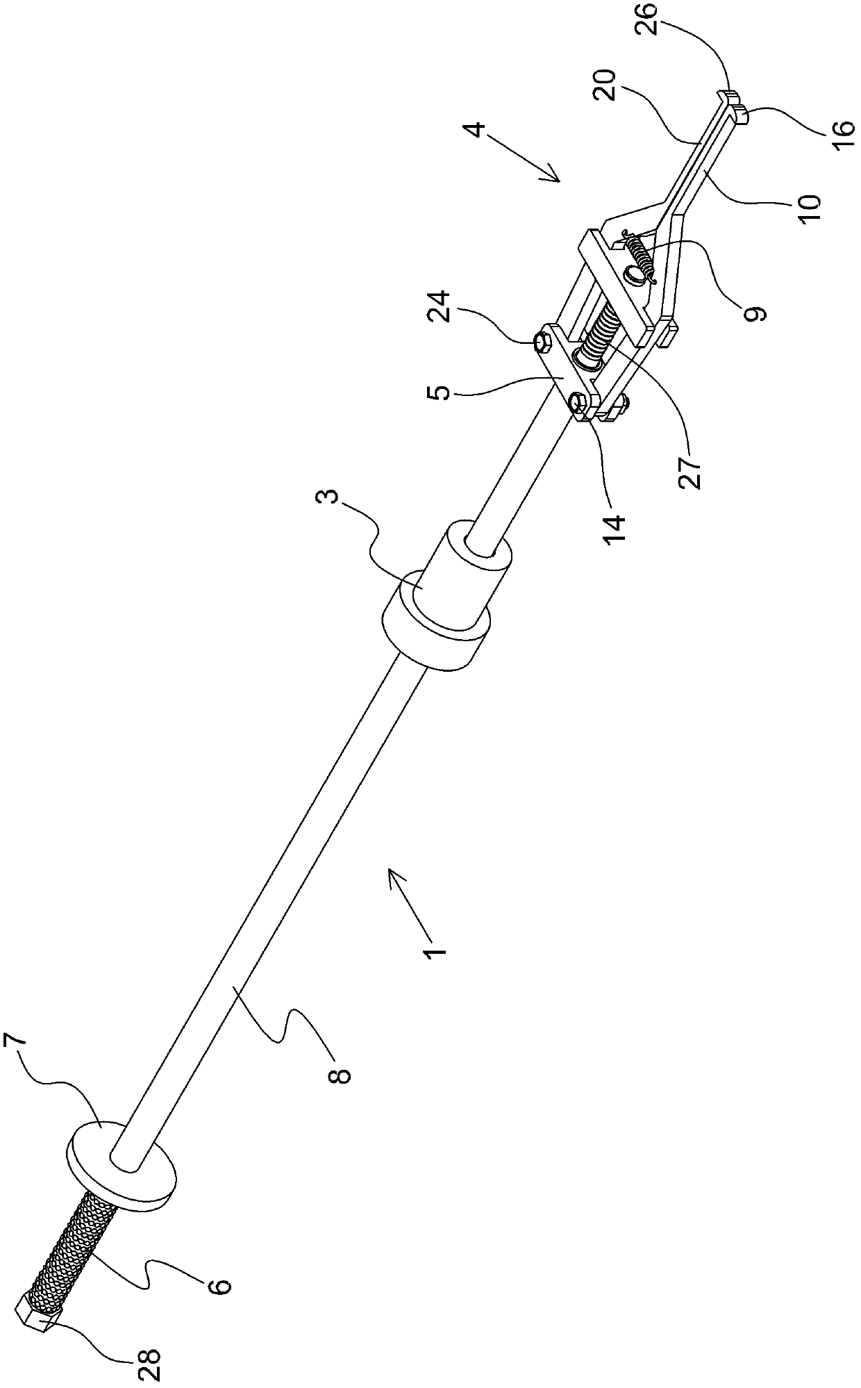
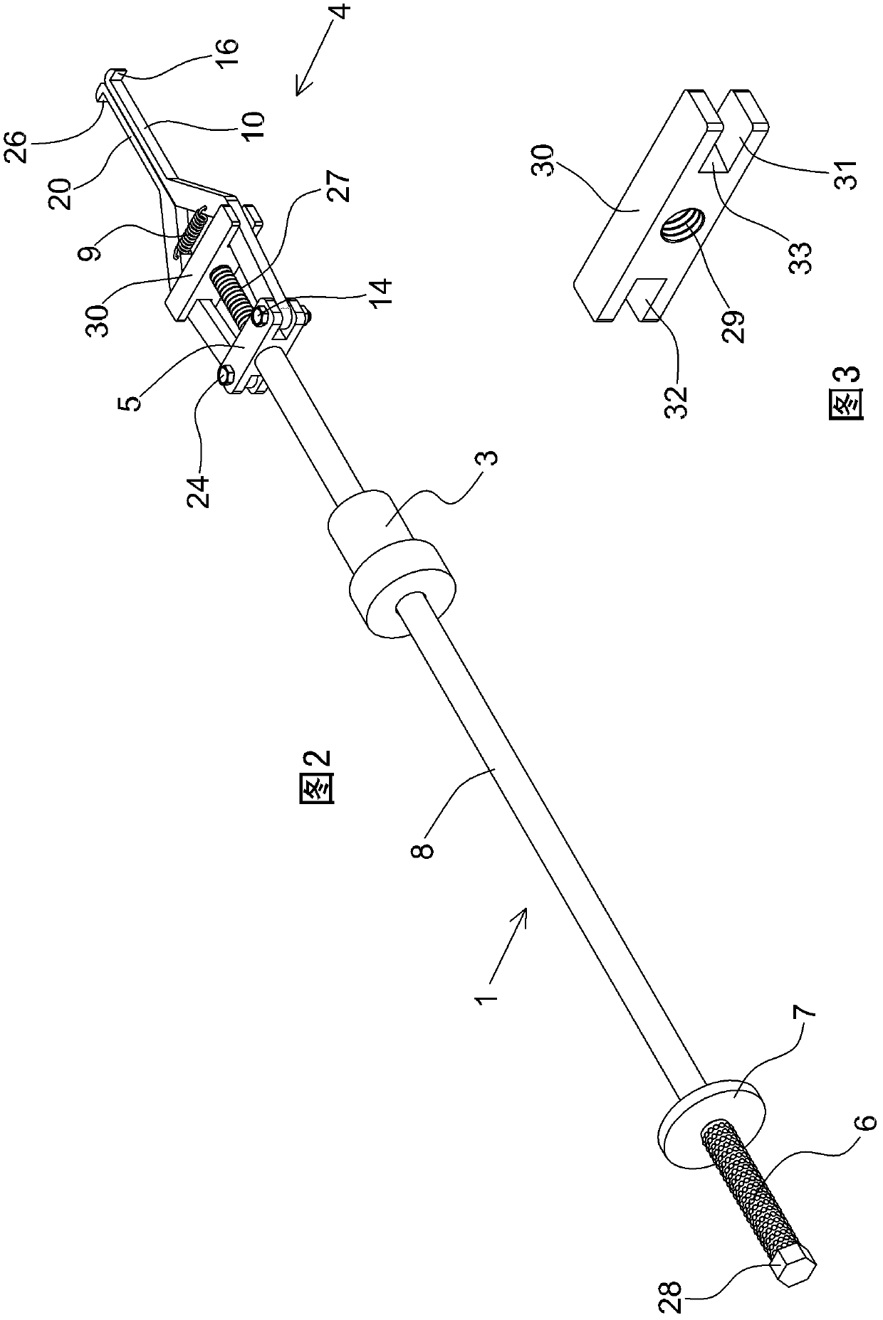
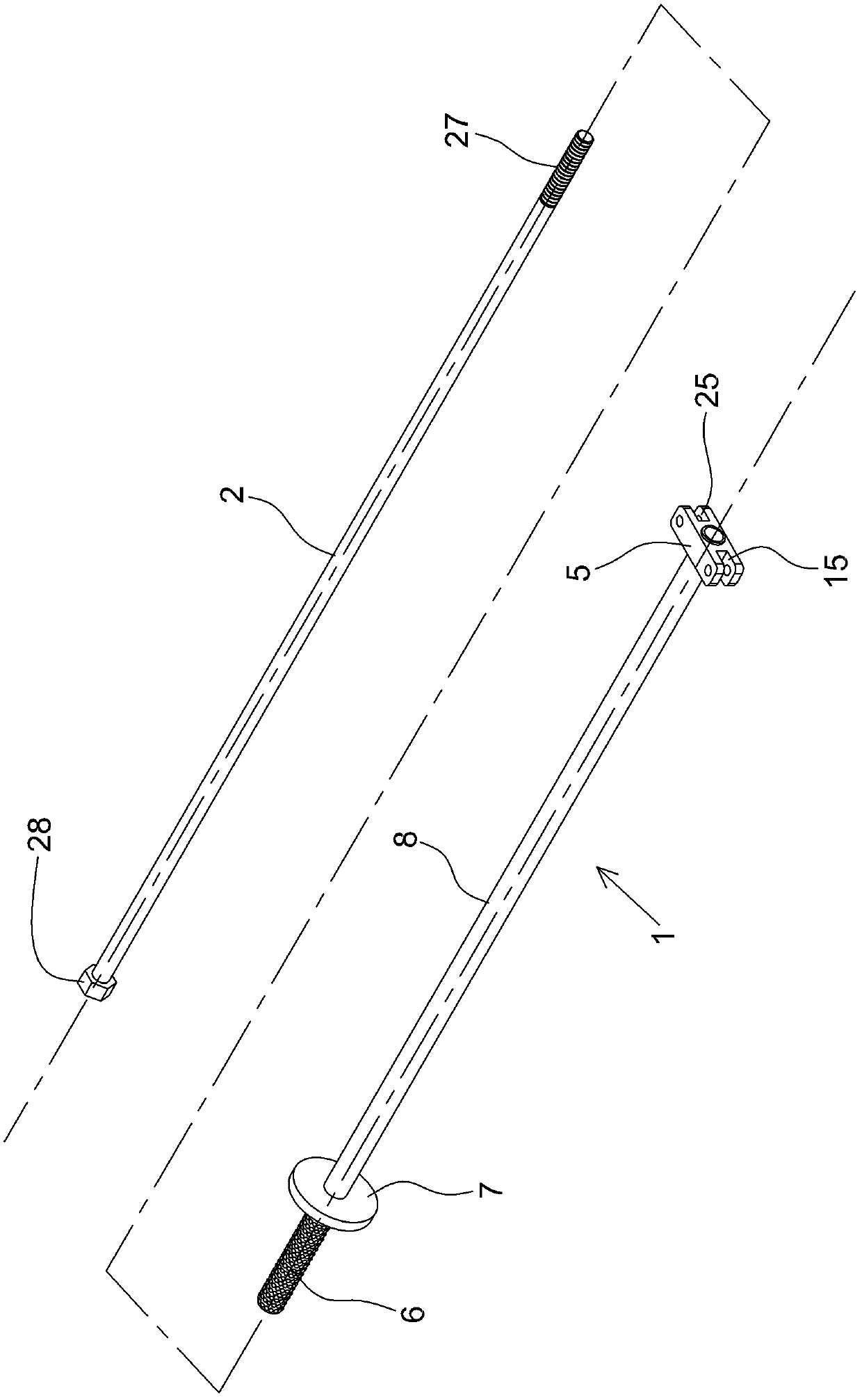
[0020] 1 handle rod 2 adjustment rod 3 impact hammer 4 jaw assembly

[0021] 5 support frame 6 handle 7 fixed disc 8 polished rod part

[0022] 9 Extension spring 10 Left claw 11 Upper arm section 12 Middle arm section

[0023] 13 Lower arm section 14 Pin shaft 15 Left ear seat 16 Left claw hook

[0024] 17 Bearing 18 Inner ring hole 19 Sheath 20 Right claw

[0025] 21 upper arm section 22 middle arm section 23 lower arm section 24 pin shaft

[0026] 25 Right ear seat 26 Right claw hook 27 Thread head 28 Hex nut

[0027] 29 threaded hole 30 tensioning slider 31 left groove 32 right groove

[0028] 33 inner end face 34 inner end face

[0029] Please refer to figure 1 , figure 2 , image 3 , Figure 4 , the present invention is an impact-type adjustable inner puller, which is composed of a handle rod 1, an adjustment rod 2, an impact hammer 3, and a claw assembly 4. The handle rod 1 is composed of a hollow tube, and the front end of the ha...


PUM


Abstract

The invention discloses an impact adjustable internal puller, which comprises a handle rod, an adjusting rod, an impact hammer and a clamping claw component, wherein the handle rod is constituted by a hollow circular tube; the front end of the handle rod is welded with a supporting frame, and the rear end of the handle rod is provided with a handle; the root part of the handle is welded with a fixed disc; the supporting frame consists of a left lug seat and a right lug seat; the impact hammer is sleeved on a polished rod part of the handle rod; the clamping claw component consists of a left pulling claw, a right pulling claw, and a tension slide block and a tension spring which are arranged between the left pulling claw and the right pulling claw; the middle part of the tension slide block is provided with a threaded hole; the adjusting rod is constituted by an iron stick and is penetrated in the handle rod; the front end of the adjusting rod is provided with a threaded head, and the rear end of the adjusting rod is provided with a hexagon nut; the threaded head at the front end of the adjusting rod is screwed with the threaded hole on the middle part of the tension slide block; and the hexagon nut at the rear end of the adjusting rod is pressed against an orifice at the rear end of the handle rod. The product is smooth to operate, convenient and easy to use, fast to disassemble, time-saving and labor-saving and is suitable for disassembling bearings of various specifications.

Description

technical field [0001] The invention belongs to the field of mechanical maintenance tools, and relates to a dismantling tool for bearings and metal sheaths or non-metal sheaths, in particular to an impact-type adjustable inner puller. Background technique [0002] In the maintenance of motor vehicles, it often occurs that the bearing cannot be removed from the outside. In such a situation, the entire wheel hub must be disassembled, and then the bearing must be removed from the inside. The operation is cumbersome, not only time-consuming, labor-intensive, and laborious The bearing and the sheath (bearing seat) are inlaid tight fit, which is not easy to start, and the dismantling project is relatively large, and it is easy to squeeze hands and touch hands, causing personal injury. [0003] For this reason, someone has designed a bearing puller, which is to bend a hook at one end of the crowbar, extend the hook into the hole of the inner ring of the bearing, hook the inner ring...

Claims


Application Information

Patent Timeline
Patent Type & Authority Patents(China)
IPC IPC(8): B25B27/067
Inventor 郑亚利谭瑞杰付桂荣霍文立
Owner 北京市环雅清扫保洁服务中心
Why Eureka
Try Eureka