A tire changer

A tire changer and tire technology, which is applied in tire installation, tire parts, transportation and packaging, etc., can solve the problems such as the lack of a simple synchronization device for the clamping device, the inability to switch between manual and automatic, and the difficulty in taking into account the tire disassembly and assembly. To achieve reasonable and convenient tire hooking, improve tire removal efficiency, and good quality of disassembly and assembly

Active Publication Date: 2017-11-07
浙江科炬源科技有限公司
View PDF8 Cites 0 Cited by
  • Summary
  • Abstract
  • Description
  • Claims
  • Application Information

AI Technical Summary

Problems solved by technology

Automobile tire dismantling machine has been generally used at present, generally includes base, frame, bead bead device, sliding frame, tire fixing device, bead bead device and tire dismantling device, prior art is used in a large number of manual operation, and manual operation not only labor High strength, low efficiency, and requires certain skills and a lot of experience, high labor requirements, long disassembly and assembly time, low degree of automation, it seems outdated in the current industry 4.0 era; the clamping device of the tire changer does not have a simple Synchronous device, the accuracy is not high, and it is easy to break down. The tire removal hook is generally fixed, and the tire needs to be pried up manually, which is very inconvenient. Moreover, the same tire changer cannot switch between manual and automatic, and it is difficult to take care of large quantities of tires of the same size. Removal and installation of individual tires of different sizes

Method used


Image

  • A tire changer
  • A tire changer
  • A tire changer

Examples


Embodiment Construction

[0025] The present invention will be described in detail below in conjunction with the accompanying drawings and specific embodiments.

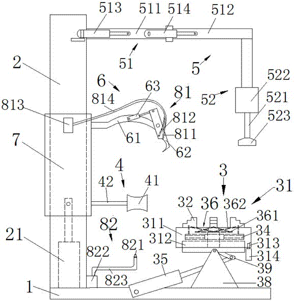
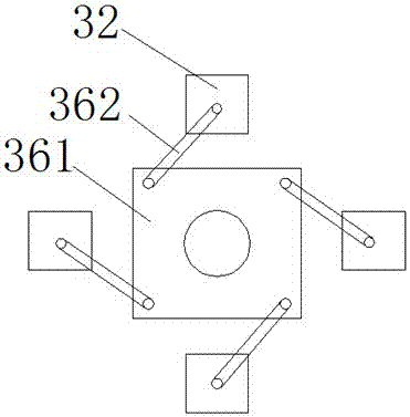
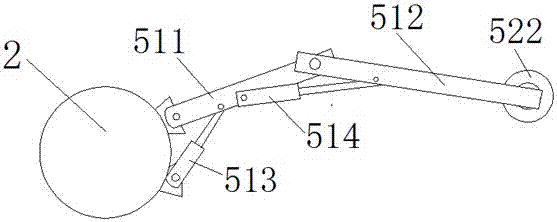
[0026] Such as figure 1 As shown, it includes a base 1, a frame 2 vertically and fixedly arranged on the base 1, an auxiliary tire pressing device 5 arranged on the upper end of the frame 2, a sliding frame 7 slidingly sleeved on the frame 2, and a The tire fixing device 3 on the base 1, the tire pressing device 4 and the tire removing device 6 arranged on the sliding frame 7 in sequence from bottom to top; fixed claw 32; as figure 2 As shown, the tire fixing device 3 is also provided with a fixed claw synchronization device 36; the fixed claw synchronization device 36 includes a synchronization disk 361 and a plurality of linkage rods 362 arranged in the middle of the turntable 31; one end of the plurality of linkage rods 362 It is hinged with the corresponding tire fixing claw 32 , and the other end is respectively hinged with the synchr...


PUM


Abstract

The invention relates to a tire dismounting machine. The tire dismounting machine comprises a base, a rack which is vertically fixed on the base, an auxiliary tire pressing device arranged at the upper end of the rack, a slide frame which slidingly sleeves the rack, a tire fixing device which is arranged on the base, and a tire pressing device and a tire dismounting device which are arranged on the slide frame in sequence from bottom to top, wherein the tire fixing device comprises a rotary table and tire fixing claws arranged on the upper end face of the rotary table; the tire fixing device is further provided with a fixing claw synchronizer; the fixing claw synchronizer comprises a synchronizing disc arranged in the middle of the rotary table and a plurality of linkage rods; one end of each of the plurality of linkage rods is hinged to the corresponding tire fixing claw and the other end of each of the plurality of linkage rods is hinged to the synchronizing disc at interval; and each linkage rod and the corresponding tire fixing claw are inclined to form a certain angle in the retracting direction of the tire fixing claw.

Description

technical field [0001] The invention relates to a tire changer and belongs to the field of automobile machinery. Background technique [0002] Tire changers are currently used to perform the disassembly and assembly operations between tires and their associated rims. After bead breaking, they can remove the tire from its rim, for example to perform maintenance or replacement work on the bladder, the rim and / or the tire itself, and then mount it or a new tire on the rim. Automobile tire dismantling machine has been generally used at present, generally includes base, frame, bead bead device, sliding frame, tire fixing device, bead bead device and tire dismantling device, prior art is used in a large number of manual operation, and manual operation not only labor High strength, low efficiency, and requires certain skills and a lot of experience, high labor requirements, long disassembly and assembly time, low degree of automation, it seems outdated in the current industry 4.0 ...

Claims


Application Information

Patent Timeline
Patent Type & Authority Patents(China)
IPC IPC(8): B60C25/132
CPCB60C25/132
Inventor 饶建明
Owner 浙江科炬源科技有限公司
Why Eureka
Try Eureka