Material transportation and transferring structure

A material and conveying unit technology, applied in the direction of conveyors, conveyor objects, transportation and packaging, etc., can solve the problems of heavy weight, increase, low efficiency, etc., to facilitate manufacturing and later maintenance, reduce safety risks, machinery The effect of simple structure

Pending Publication Date: 2020-11-27
灵璧久工精密钢管制造有限公司
View PDF0 Cites 4 Cited by
  • Summary
  • Abstract
  • Description
  • Claims
  • Application Information

AI Technical Summary

Problems solved by technology

In small and medium-sized enterprises, in order to save costs, manual handling is generally used. However, on the one hand, manual handling will cause great safety hazards, and on the other hand, it will be inefficient and affect the overall benefits of the enterprise.
Especially when handling shaft materials with a relatively long length, the characteristics of its long length and heavy weight further aggravate the above-mentioned defects, which need to be solved urgently

Method used


Image

  • Material transportation and transferring structure
  • Material transportation and transferring structure
  • Material transportation and transferring structure

Examples


Embodiment Construction

[0038] For ease of understanding, the specific structure and working method of the present invention will be further described below in conjunction with the accompanying drawings.

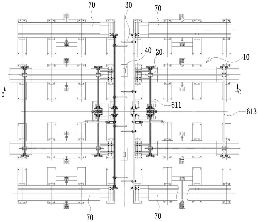
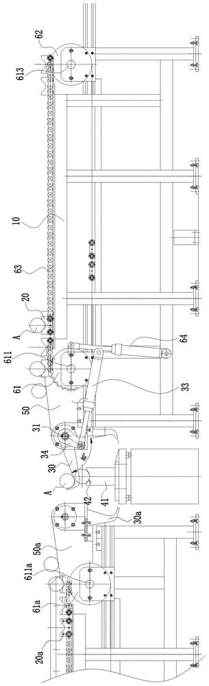
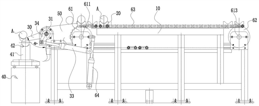
[0039]A material conveying and transshipment structure, comprising a frame 10, on which a first conveying unit for transporting shaft materials A is provided, and on the first conveying unit is provided a material conveying trolley that moves synchronously with it 20. The downstream end of the first conveying unit is provided with a transfer unit, the transfer unit includes a transfer hook 30, and the transfer hook 30 is in the upper position or the lower position when it swings under the action of the hook driving unit state blanking station, the swing end of the transfer hook 30 is hook-shaped for restraining the shaft material A; the transfer unit also includes a blanking table 40 for placing the shaft material A, and the blanking table 40 is located at the blanking station of the transfer hook ...


PUM


Abstract

The invention belongs to the technical field of transportation machinery, and particularly relates to a material transportation and transferring structure for shaft type materials or column type materials. The structure comprises a rack; a first transportation unit which is used for delivering the shaft type materials is arranged on the rack; a material delivering trolley is arranged on the firsttransportation unit and moves synchronously with the first transportation unit; a transferring unit is arranged at the downstream end of the first transportation unit; the transferring unit comprisesa transferring falcula; the transferring falcula sways under the action of a falcula driving unit and is positioned at a material receiving station in an upper position status or at a material fallingstation in a lower position status; a swaying end of the transferring falcula is in a hook shape and is used for restraining the shaft type materials; the transferring unit further comprises a material falling platform which is used for placing the shaft type materials; and the material falling platform is positioned at the material falling station of the transferring falcula and the height of amaterial receiving position of the material falling platform is higher than the height of the material falling station of the transferring falcular. Automatic transportation and transferring of the shaft type materials are realized, the safety risk is lowered, and the production efficiency is improved at the same time.

Description

technical field [0001] The invention belongs to the technical field of conveying machinery, and in particular relates to a shaft or column material conveying and transfer structure. Background technique [0002] In a shaft or column material production enterprise, after the material production is completed, the shaft material needs to be conveyed or transshipped. In small and medium-sized enterprises, in order to save costs, manual handling is generally used. However, on the one hand, manual handling will cause great safety hazards, and on the other hand, it will be inefficient and affect the overall benefits of the enterprise. Especially when handling shaft materials with a relatively long length, the characteristics of its long length and heavy weight further aggravate the above-mentioned defects and need to be solved urgently. Contents of the invention [0003] The object of the present invention is to provide a material conveying and transferring structure, which real...

Claims


Application Information

Patent Timeline
Patent Type & Authority Applications(China)
IPC IPC(8): B65G47/82B65G47/52B65G17/12B65G17/36
CPCB65G17/123B65G17/36B65G47/52B65G47/82
Inventor 冯辉华仁祥徐文豪
Owner 灵璧久工精密钢管制造有限公司
Why Eureka
Try Eureka