Slag cleaning plant for flame cutting machine

A flame cutting machine and slag cleaning technology, which is applied to gas flame welding equipment, welding equipment, metal processing equipment, etc., can solve the problems of complex structure and insufficient safety of the slag cleaning device, and achieve simple structure and no mechanical wear. , the effect of simplifying the overall structure

Inactive Publication Date: 2017-11-03
西安珀尔电子科技有限公司
View PDF1 Cites 4 Cited by
  • Summary
  • Abstract
  • Description
  • Claims
  • Application Information

AI Technical Summary

Problems solved by technology

[0006] In order to solve the problems of complex structure and insufficient safety of the slag cleaning device of the existing flame cutting machine, the present invention designs a slag cleaning device of the flame cutting machine

Method used


Image

  • Slag cleaning plant for flame cutting machine
  • Slag cleaning plant for flame cutting machine
  • Slag cleaning plant for flame cutting machine

Examples


Embodiment 1

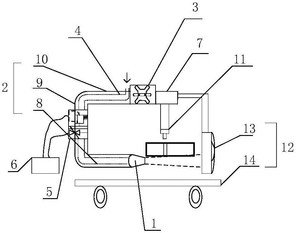
[0033] In order to solve the problems of complex structure and low safety existing in the slag cleaning device of the existing flame cutting machine, a device such as figure 1 The slag cleaning device of the flame cutting machine shown includes a slag blowing gun head 1 , a gun head bracket 2 , a fixed bracket 3 , an air inlet pipe 4 , a dual control valve 5 and a control device 6 . The slag blowing torch head 1 is connected to the cutting torch head guide rail 7 of the flame cutting machine through the fixed bracket 3, so that the slag blowing torch head 1 and the cutting torch head 11 move synchronously. The fixed bracket 3 includes two clamping parts, the position of the fixed bracket on the cutting gun head guide rail 7 can be adjusted by loosening the bolts (or other fixing parts) on the two clamping parts, and the end of the fixed bracket 3 is connected to the flame cutting On the device, for example, it is installed on the positioning clamp of the flame cutting device. ...

Embodiment 2

[0045] The difference between this embodiment and embodiment 1 is only:

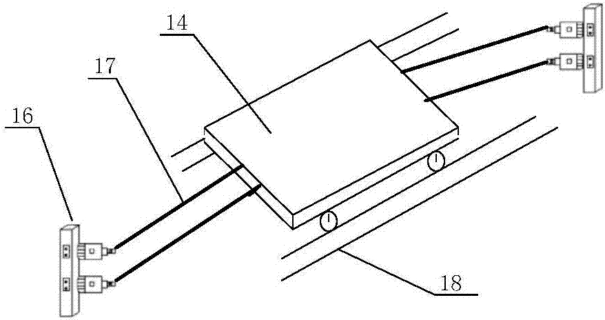
[0046] Such as image 3 As shown, the collecting plate 14 of the flame cutting machine slag cleaning device is slidingly connected with the channel steel 18 under the working platform of the flame cutting machine through the pulley at the bottom. Hand-operated device 16 and steel wire 17 are also set on collecting dish 14, and hand-operated device 16 is divided into two, and one is connected with the front end of collecting dish 14 by steel wire 17, and another is connected with the rear end of collecting dish 14 by steel wire 17. The side away from the working platform of the flame cutting machine is the front end. The hand-cranking device is a conventional reel structure, and the handles of different hand-cranking devices 16 are shaken, so that the steel wire pulls the collecting plate 14 to slide in different directions along the channel steel 18, and moves out of the working platform to realize the ...


PUM


Abstract

The invention specifically relates to a slag cleaning device for a flame cutting machine, comprising a slag blowing gun head connected to a cutting torch head guide rail of a flame cutting machine through a fixed bracket, the slag blowing torch head can move synchronously with the cutting torch head, The purge surface of the slag blowing torch head is perpendicular to the cutting surface of the cutting torch head, and the slag blowing torch head is supplied by the air inlet pipe passing through the torch head bracket to blow the slag away from the surface of the cutting material, including The slag collection device can collect the slag blown away from the cutting surface. In the slag cleaning device of the flame cutting machine of the present invention, the slag blowing gun head is connected with the cutting torch head guide rail of the flame cutting machine through a fixed bracket, thereby realizing the synchronous movement of the slag blowing torch head and the cutting torch head; The slag blowing gun head is designed with a separate moving mechanism, which simplifies the structure and ensures the accurate position of the blowing slag. A slag collection device specially designed to collect slag avoids slag splashing and burns the operator, which is safer.

Description

technical field [0001] The invention belongs to the technical field of flame cutting, and in particular relates to a slag cleaning device for a flame cutting machine. Background technique [0002] In the metal processing industry, it is often necessary to cut metal sheets and pipes. Currently, the commonly used cutting methods include flame cutting, plasma cutting, and laser cutting. Flame cutting is to preheat the cutting part of the workpiece to a certain temperature by using the heat energy of the flame mixed with combustible gas and oxygen, and then spray a high-speed cutting oxygen flow to oxidize the metal violently and release heat, and use the cutting oxygen flow to melt the metal oxide in the molten state. Blow off while achieving the cutting method. Flame cutting machine can cut large-thickness plate. At present, the domestic technology can cut 2000mm thick steel plate. The cutting equipment and cutting cost are relatively low, and the pollution is less than that ...

Claims


Application Information

Patent Timeline
Patent Type & Authority Applications(China)
IPC IPC(8): B23K7/00B23K7/10
CPCB23K7/00B23K7/10
Inventor 畅通
Owner 西安珀尔电子科技有限公司
Why Eureka
Try Eureka