Screw rod for pushing trolley

A technology of screw and trolley, which is applied in the direction of packaging, etc., can solve the problems of difficult welding of fan-shaped plates, high cost, and difficulty in welding spiral strip plates, and achieves the effects of easy support, simple operation, and simple and easy manufacturing

Active Publication Date: 2015-07-08
DAIFUKU CO LTD
View PDF8 Cites 0 Cited by
  • Summary
  • Abstract
  • Description
  • Claims
  • Application Information

AI Technical Summary

Problems solved by technology

[0004] In the framework of the prior art described in the above-mentioned Patent Document 1, it is not easy to arrange the fan-shaped plate material constituting the connecting member at a predetermined position inside the helical belt plate constituting the cylindrical screw body, and even if it is disposed at The inner periphery of the fan-shaped plate at a predetermined position on the inner side of the spiral strip plate is relatively easy to weld to the peripheral surface of the drive shaft, but it is still quite difficult to weld the outer periphery of the fan-shaped plate to the inner surface of the spiral strip plate, so more steps and time, resulting in higher cost

Method used


Image

  • Screw rod for pushing trolley
  • Screw rod for pushing trolley
  • Screw rod for pushing trolley

Examples


Embodiment Construction

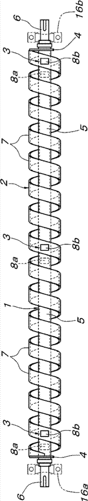
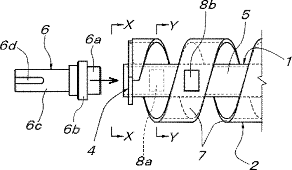
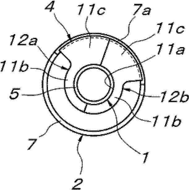
[0048] Figure 1A to Figure 2B Among them, 1 is a drive shaft, 2 is a cylindrical screw body, 3 is a connecting member, and 4 is an end plate. The drive shaft 1 is composed of a cylindrical body 5 that is slightly longer than the overall length of the cylindrical screw body 2, and an end shaft body 6 that is concentrically fixed to both ends of the cylindrical body and protrudes from both ends of the cylindrical screw body 2. . The end shaft body 6 is composed of a fitting portion 6a embedded in the end of the cylindrical body 5, a large-diameter collar portion 6b connected to the end of the cylindrical body 5, and a small-diameter shaft body 6c having a keyway 6d. constituted. The fitting part 6a is inserted into the end of the cylindrical body 5, and the cylindrical body 5 and the end shaft body 6 are integrated by welding in a state where the large-diameter collar portion 6b is in contact with the end of the cylindrical body 5.

[0049]The cylindrical screw body 2 is com...


PUM


Abstract

PROBLEM TO BE SOLVED: To reduce manufacturing cost of a screw for carriage propulsion which is applicable to a carriage type conveying apparatus of a screw-drive system. SOLUTION: The screw for carriage propulsion comprises a driving shaft 1, a cylindrical screw body 2 externally fit onto the driving shaft 1 concentrically, and a connection means 3 integrating the driving shaft 1 with the cylindrical screw body 2. In the screw for carriage propulsion, each of the connection means 3 comprises rod-like bodies 8a, 8b radially penetrating through a band-like spiral plate 7 constituting the cylindrical screw body 2 at a plurality of parts in the axis direction of the cylindrical screw body 2, the inner ends 9 of the rod-like bodies 8a, 8b are welded to a peripheral face of the driving shaft 1, and the peripheral faces of the rod-like bodies 8a, 8b outwardly protruded from the band-like spiral plate 7 are welded to an outer face of the band-like spiral plate 7. COPYRIGHT: (C)2012,JPO&INPIT

Description

technical field [0001] The present invention relates to a trolley propulsion screw composed of a drive shaft, a cylindrical screw body concentrically fitted outside the drive shaft, and a connecting member integrating the drive shaft and the cylindrical screw body Background technique [0002] Such a trolley propulsion screw is described in Patent Document 1, and is a member for propelling various conveyance trolleys along a traveling path. The passive rollers provided on the transport trolley are fitted between the helical belt plates constituting the cylindrical screw body to rotate and drive the cylindrical screw body, thereby moving the transport trolley to the The trolley is propelled in the axial direction of the screw. As described in Patent Document 1, in the existing screw for propulsion of this trolley, the connecting member that integrates the drive shaft and the cylindrical screw body will be interposed by the helical belt plate that constitutes the cylindrical ...

Claims


Application Information

Patent Timeline
Patent Type & Authority Patents(China)
IPC IPC(8): B65G33/04B65G33/26
Inventor 井场敏之
Owner DAIFUKU CO LTD
Why Eureka
Try Eureka