Knot tying machine

A technology of knotting machine and casing, applied in the field of knotting machine, can solve the problems of low production efficiency, no mechanization, increased production cost, etc., and achieve the effect of simple and convenient structure

Inactive Publication Date: 2012-07-04
潘国良
View PDF8 Cites 4 Cited by
  • Summary
  • Abstract
  • Description
  • Claims
  • Application Information

AI Technical Summary

Problems solved by technology

Now in the scarf industry, the ends of the scarves are all knotted manually without mechanization, which results in slow production progress and low production efficiency of the above-mentioned style scarves, and due to a large amount of labor input, the production cost increases.

Method used


Image

  • Knot tying machine
  • Knot tying machine
  • Knot tying machine

Examples


Embodiment 1

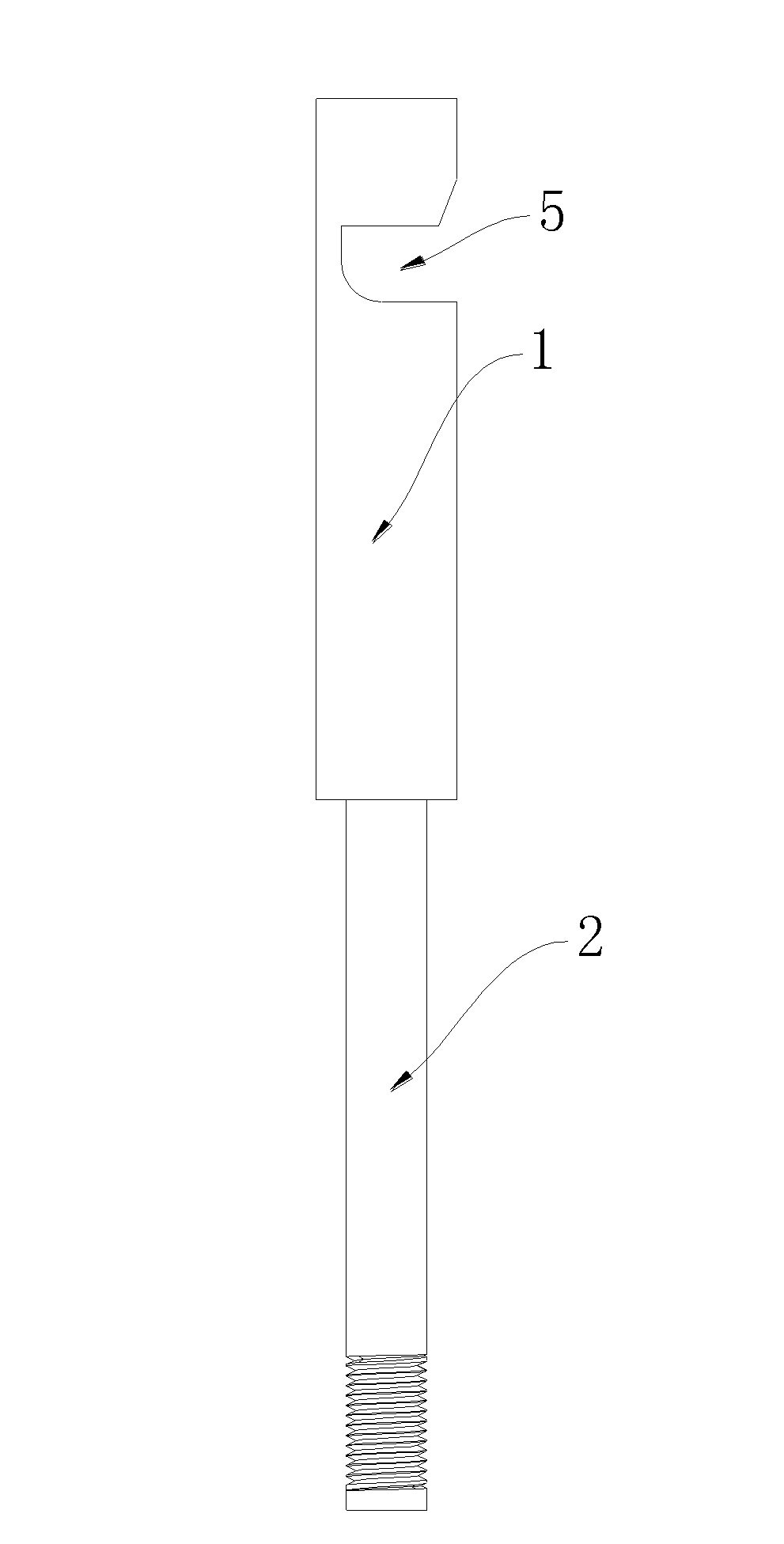
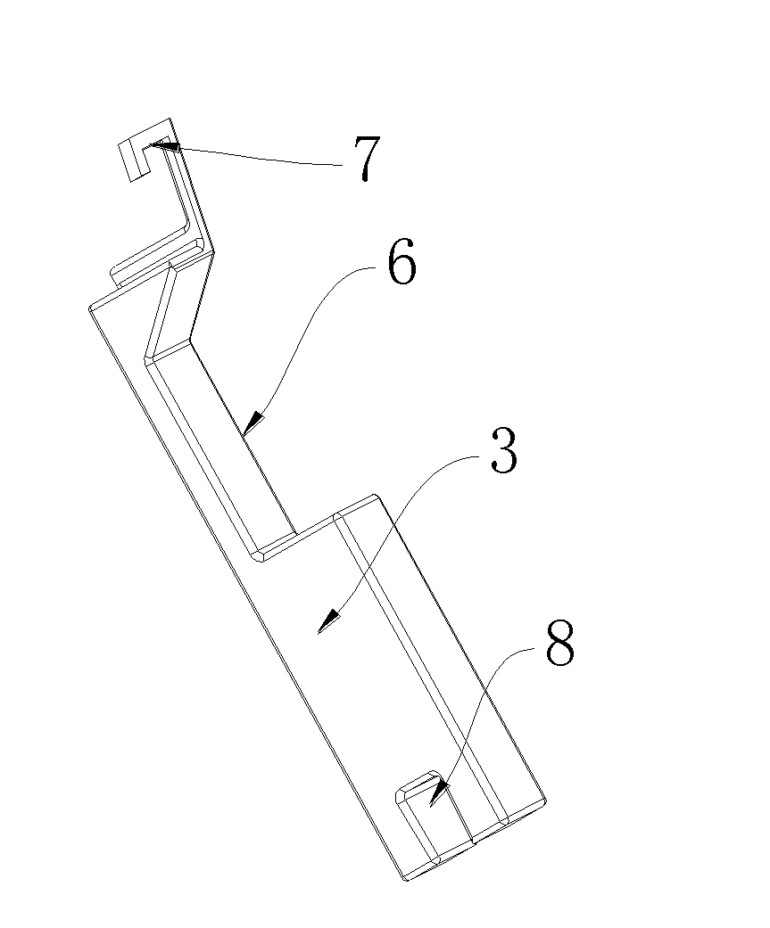
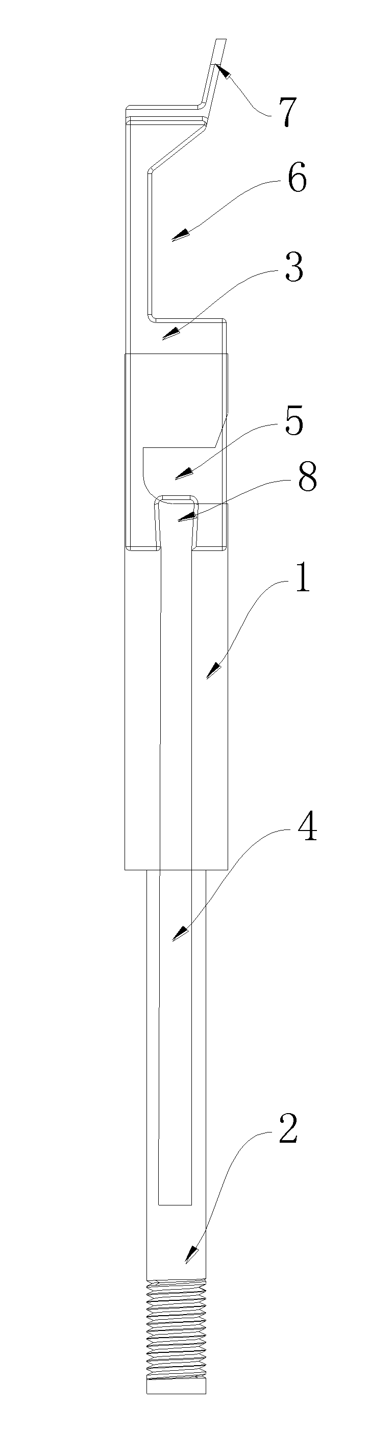
[0012] like figure 1 , figure 2 , image 3 , Figure 4 As shown, the knotting machine described in this embodiment mainly includes a casing 1, which is a flat cuboid shape, hollow, and a connecting pipe 2 is provided at the bottom, and a notch 5 is provided at the upper end of the casing 1, and the notch 5 The side of the upper casing 1 is chamfered, and the machine head 3 is arranged inside the casing 1. The machine head 3 is matched with the casing 1. The upper end of the machine head 3 is provided with a notch on the same side as the notch 5 on the casing 1. 6. The upper side of the notch 6 has an inclined transition, the length of the notch 6 is greater than the length of the notch 5, and a right-angle hook 7 is arranged on the top of the machine head 3, and the right-angle hook 7 is on the same side as the front of the notch 6, and the right-angle hook 7 is set on an outward slope. A bayonet 8 is provided at the bottom of the machine head 3, and the bayonet 8 is conne...

specific Embodiment approach

[0013] Specific implementation method: the head 3 of the knotting machine is inside the casing 1, the notch 5 and the notch 6 are at the same position, and the right-angle hook 7 is outside the casing 1, and the two ends of the rope are clamped and then inserted into the notch 5 Inside, both ends are pulled upwards, the casing 1 drives the machine head 3 to rotate 270° toward the opening of the right-angle hook 7, the right-angle hook 7 hooks one end of the rope, the push rod 4 pulls the machine head 3 to retract into the casing 1, and the notch 5 The rope at the place slides down and moves upwards to realize the knotting of the rope.


PUM


Abstract

The invention relates to a knot tying machine. The knot tying machine mainly comprises a machine shell, wherein the machine shell has a flat rectangular shape and is hollow; the bottom of the machine shell is provided with a connecting pipe; the upper end of the machine shell is provided with a notch; the notch and the lateral side of the machine shell at the upper end are chamfered; a machine head is arranged in the machine shell and is matched with the machine shell; the upper end of the machine head on the same side as the notch on the machine shell is provided with a recess; the upper side of the recess is in slope transition; the length of the recess is longer than that of the notch; the top part of the machine head is provided with a right angle hook; the right angle hook and the front side of the notch are on the same lateral surface; the right angle hook is outward-inclined; the bottom of the machine head is provided with a bayonet; the bayonet is connected with a pushing rod; and the pushing rod is arranged in the connecting pipe. According to the knot tying machine, the machine shell and the connecting pipe have a hollow structure, and the machine head and the pushing rod are arranged in the machine shell, so that the relative displacement is changed. The upper parts of the machine shell and the machine head are provided with the notch and the recess respectively, and the top part of the machine head is provided with the right angle hook, so that a rope is knotted through the structures of the notch, the recess and the right angle hook, and the knot tying machine is simple in structure and convenient.

Description

technical field [0001] The invention relates to the field of scarf production equipment, in particular to a knotting machine. Background technique [0002] The scarf is a kind of scarf ornament for men and women to decorate and keep out the cold. In many places, scarves are made of twist-like ropes at both ends, and there is a non-slip knot at the end of each rope, especially in Europe, America and Arab countries. The styles are all popular from hundreds of years ago to the present day. And now in the scarf industry, the ends of the scarves are knotted manually without mechanization, so the production progress of the above-mentioned scarves is slow, the production efficiency is low, and due to the large amount of labor input, the production cost increases. Contents of the invention [0003] The object of the present invention is to provide a scarf knotting machine with high knotting efficiency and low operating cost in order to solve the above technical deficiencies. [...

Claims


Application Information

Patent Timeline
Patent Type & Authority Applications(China)
IPC IPC(8): D04G5/00A41D23/00
Inventor 潘国良
Owner 潘国良
Why Eureka
Try Eureka