Knotting device

A technology of knotter and transmission structure, applied in the field of knotter, can solve the problem of unstable cutting of suture by a shearing knife, and achieve the effect of stable and reliable structure and solving instability

Pending Publication Date: 2020-06-23
BEIJING MED ZENITH MEDICAL SCI CORP LTD
View PDF0 Cites 4 Cited by
  • Summary
  • Abstract
  • Description
  • Claims
  • Application Information

AI Technical Summary

Problems solved by technology

[0004] The main purpose of the present invention is to provide a knotter, to solve the problem that the shearing knife of the knotter in the prior art is unstable when cutting the suture

Method used


Image

  • Knotting device
  • Knotting device
  • Knotting device

Examples


Embodiment Construction

[0023] It should be noted that, in the case of no conflict, the embodiments in the present application and the features in the embodiments can be combined with each other. The present invention will be described in detail below with reference to the accompanying drawings and examples.

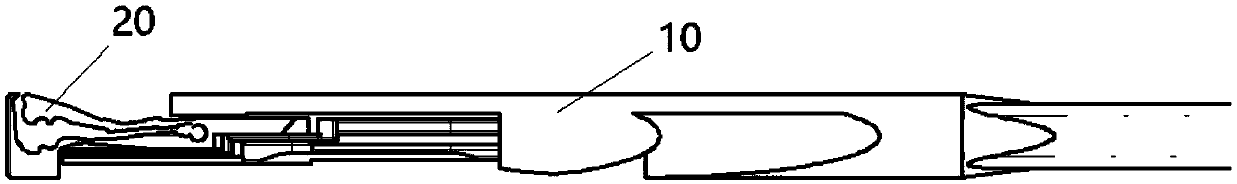
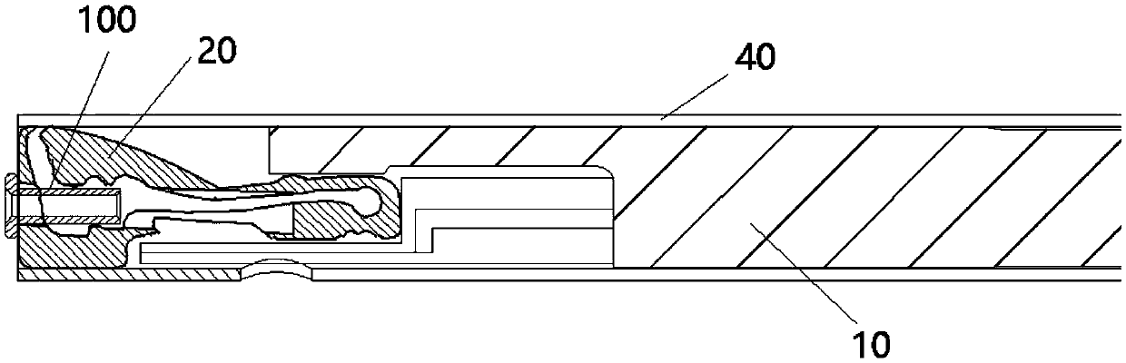
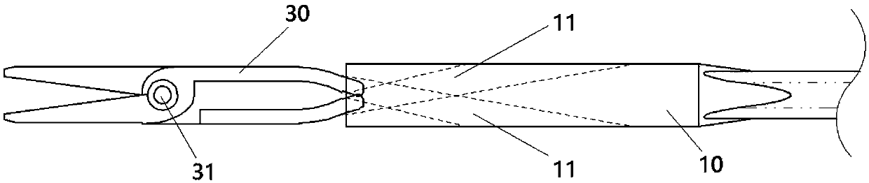
[0024] Such as Figure 1 to Figure 4 As shown, the knotter of this embodiment includes: a transmission structure 10 , a punching clip 20 and scissors 30 . The jaw of the punching clip 20 has a first position in an open state, and a second position driven by the transmission structure 10 for punching. The scissors 30 have a first position in an open state driven by the transmission structure 10 , and a second position in a cutting state driven by the transmission structure 10 . The second position of the scissors 30 is synchronized with the second position of the punching clip 20 .

[0025] Applying the technical solution of this embodiment, when the suture is knotted, the transmission struct...


PUM


Abstract

The invention provides a knotting device. The knotting device comprises a transmission structure, a punching and shearing clip and scissors; the opening of the punching and shearing clip has a first position in an opening state and a second position in a punching state when being driven by the transmission structure; the scissors have a first position in an opening state when being driven by the transmission structure and a second position in a shearing state when being driven by the transmission structure; and the second position of the scissors and the second position of the punching and shearing clip are synchronous. The technical scheme in the invention effectively solves the problem that the shearing knife of the knotting device in the prior art is non-steady while cutting off a suture line.

Description

technical field [0001] The invention relates to the technical field of medical instruments, in particular to a knotter. Background technique [0002] In recent years, with the development of surgical instruments and cardiac surgery techniques, minimally invasive surgery has become a hot spot in the development of various surgical disciplines. Minimally invasive surgery has the characteristics of small incision and fast recovery. At the same time, it requires the operator to realize simple and fast postoperative suturing and knotting in a minimally invasive surgical environment. There are two kinds of knotting methods used clinically: manual knotting and instrumental knotting. [0003] Existing surgical knotters generally clamp the sutures by plastically deforming the clamping parts through punching and shearing clips, and then cut the sutures by cutting knives or shearing knives. The disadvantages of this cutting method are: when using a cutting knife to cut, first, the cu...

Claims


Application Information

Patent Timeline
Patent Type & Authority Applications(China)
IPC IPC(8): A61B17/04
CPCA61B17/0469A61B2017/0496A61B17/0487A61B2017/0488A61B17/0467A61B2017/0474A61B2017/047
Inventor 马志伟张志武可大年周庆亮孟坚
Owner BEIJING MED ZENITH MEDICAL SCI CORP LTD
Why Eureka
Try Eureka