Floor drain

A floor drain and water seal technology, applied in the field of components, can solve the problems of easy clogging and long service life of the floor drain, and achieve the effect of not being easy to clog

Inactive Publication Date: 2013-08-28
MAIN PLAN NINGBO BATHROOM COLLECTIONS
View PDF1 Cites 7 Cited by
  • Summary
  • Abstract
  • Description
  • Claims
  • Application Information

AI Technical Summary

Problems solved by technology

[0004] The invention overcomes the shortcoming that the existing floor drain is easy to be blocked when it is used for a long time, and provides a floor drain that is not easy to be blocked even if it is used for a long time

Method used


Image

  • Floor drain
  • Floor drain
  • Floor drain

Examples


Embodiment 1

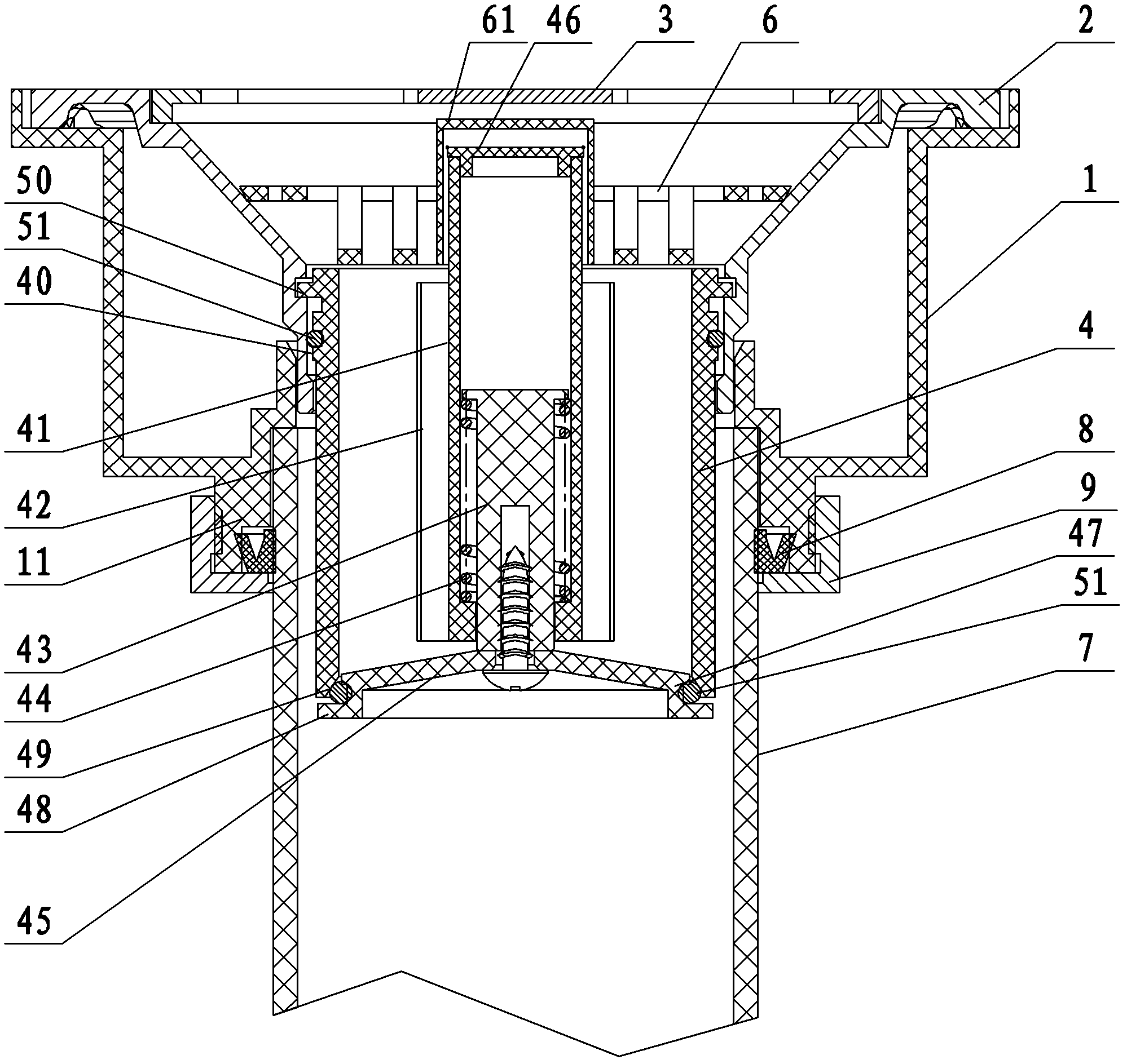
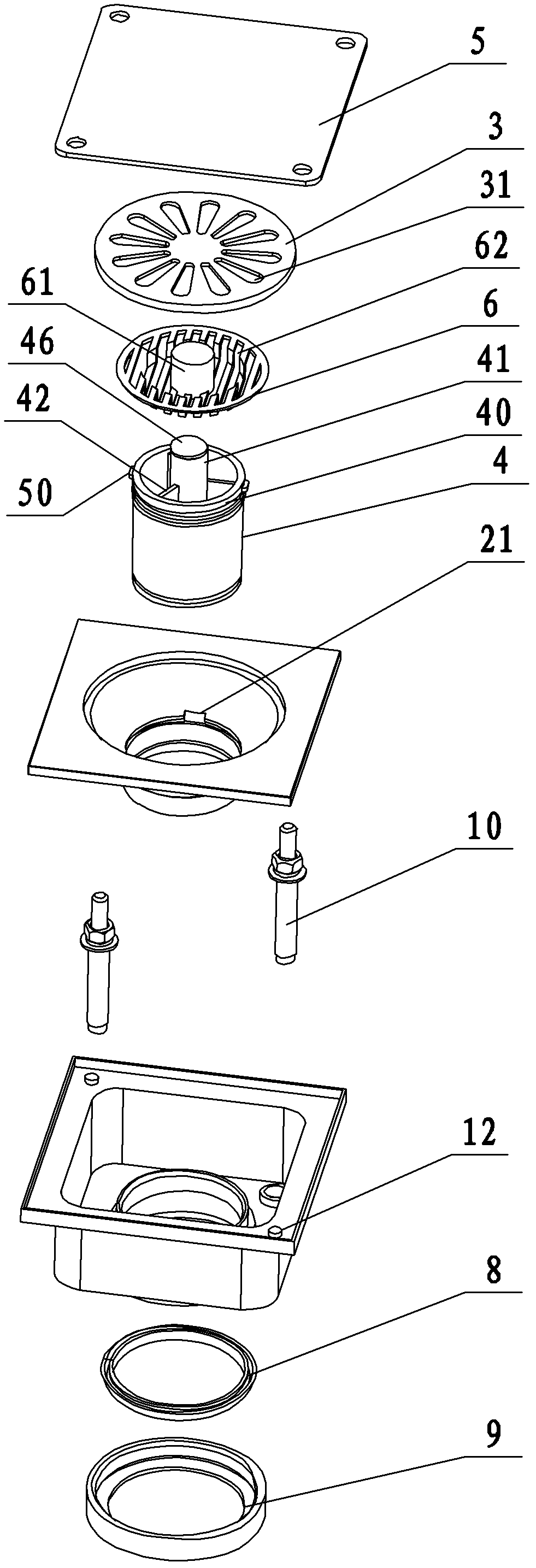
[0023] Example 1: A floor drain (see attached figure 1 , Attached Figure 4 ), including the embedded box 1, the floor drain frame 2 installed in the embedded box 1, the filter cover 3 installed at the upper end of the floor drain frame 2, the embedded box 1 is square, the embedded box 1 is installed in the embedded hole, and the The upper surface of the upper edge of the buried box 1 is provided with a supporting column 12 at a diagonal position, and a protective cover 5 is detachably connected to the supporting column 12. The protective cover 5 covers the upper opening of the embedded box 1 to prevent debris Enter the embedded box 1 and drain pipe 7. The four corner positions of the protective cover 5 are respectively provided with a connecting hole that is adapted to connect with the support column 12, and the four connecting holes are provided to facilitate the installation and connection of the protective cover 5. The bottom surface of the embedded box 1 is provided with a...

Embodiment 2

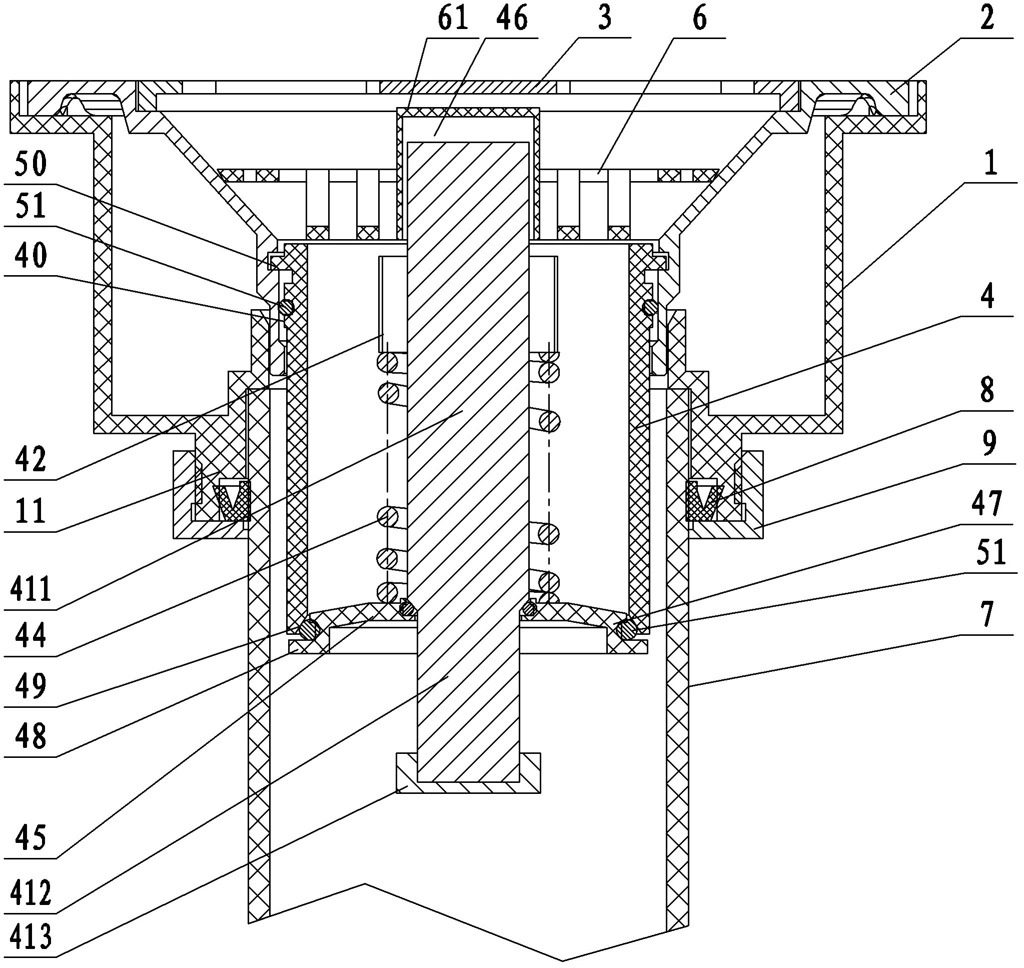
[0025] Example 2: A floor drain (see attached figure 2 ), the structure is similar to Example 1. A connecting rib is connected between the connecting column and the water seal body, the connecting rib is close to the upper end of the water seal body, a through hole is arranged in the middle of the sealing cover, and the lower end of the connecting column passes through the through hole. The connecting column is divided into an upper column 411 and a lower column 412. The outer diameter of the lower column is smaller than that of the upper column. The spring is sleeved on the outer side wall of the upper column of the connecting column, the upper end of the spring is fixedly connected to the connecting rib, and the lower end of the spring is fixedly connected to the seal At the upper end of the cover, the spring is always in tension. The end of the lower column is connected with a limit cap 413, and the outer diameter of the limit cap is larger than the diameter of the through ...


PUM


Abstract

The invention discloses a floor drain, which aims at solving the defect that an existing floor drain is easy to be blocked after being used for a long time, and comprises an embedded box, a floor drain frame and a filter cover, wherein the floor drain frame is arranged in the embedded box, the filter cover is arranged on the upper end of the floor drain frame, a hollow water seal main body which is broken over upper and lower is sleeved in the floor drain frame, a connecting column is arranged in the water seal main body, the connecting column is connected with a sealing cover through a spring, and the sealing cover and the lower end surface of the water seal main body are born against and the lower end surface of the water seal main body is covered by the sealing cover. The sealing coverdownwardly moves under the action of water pressure, sewage starts to be drained, and the sealing cover is pulled up to cover the lower end surface of the water seal main body after the sewage is drained because of elastic action of the spring, thereby having deodorant function. The sealing cover downwardly moves under the action of the water pressure, the sealing cover is not easy to be blocked to move even though sundries exist on the sealing cover, and the floor drain is not easy to be blocked after being used for a long time.

Description

Technical field [0001] The invention relates to a component used in conjunction with a sewer, more specifically, it relates to a floor drain that is not easy to be blocked. Background technique [0002] Floor drains are now designed and installed on the floors of the kitchens, bathrooms, and balconies of buildings to discharge sewage. Most of the existing floor drains have the function of deodorization, and their structure mainly includes a floor drain body, a screen and a floor drain cover. The screen is installed inside the floor drain body to prevent large debris from falling into the water pipe of the sewer. The floor drain cover is set on the floor drain body. The upper port prevents large debris from falling into the main body of the floor drain. The floor drain of this structure has been used for a long time, and debris on the screen will accumulate, which will cause the floor drain to be blocked. [0003] Chinese Patent Announcement No. CN100451252C, the announcement d...

Claims


Application Information

Patent Timeline
Patent Type & Authority Patents(China)
IPC IPC(8): E03F5/04E03C1/282E03C1/298
Inventor 施清海
Owner MAIN PLAN NINGBO BATHROOM COLLECTIONS
Why Eureka
Try Eureka