Automatic compensation clutch and realizing method for automatic compensation clutch

An automatic compensation and clutch technology, applied in the direction of mechanical drive clutches, clutches, friction clutches, etc., can solve the problems of complex structure, reduce the reliability of the actuator, and difficult to control, and achieve the effect of improving stability.

Active Publication Date: 2014-01-29
UNITED AUTOMOTIVE ELECTRONICS SYST
View PDF3 Cites 0 Cited by
  • Summary
  • Abstract
  • Description
  • Claims
  • Application Information

AI Technical Summary

Problems solved by technology

The disadvantage of this solution is: adding a self-adjusting push rod in the actuator makes the structure complicated and also reduces the reliability of the entire actuator
No matter which solution has the problem of complex structure and difficult control

Method used


Image

  • Automatic compensation clutch and realizing method for automatic compensation clutch
  • Automatic compensation clutch and realizing method for automatic compensation clutch
  • Automatic compensation clutch and realizing method for automatic compensation clutch

Examples


Embodiment Construction

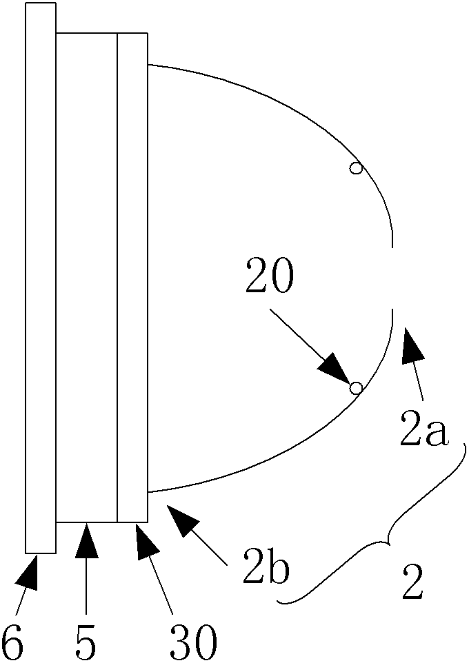
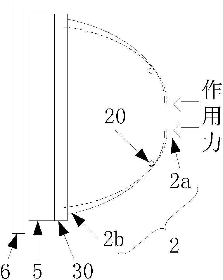
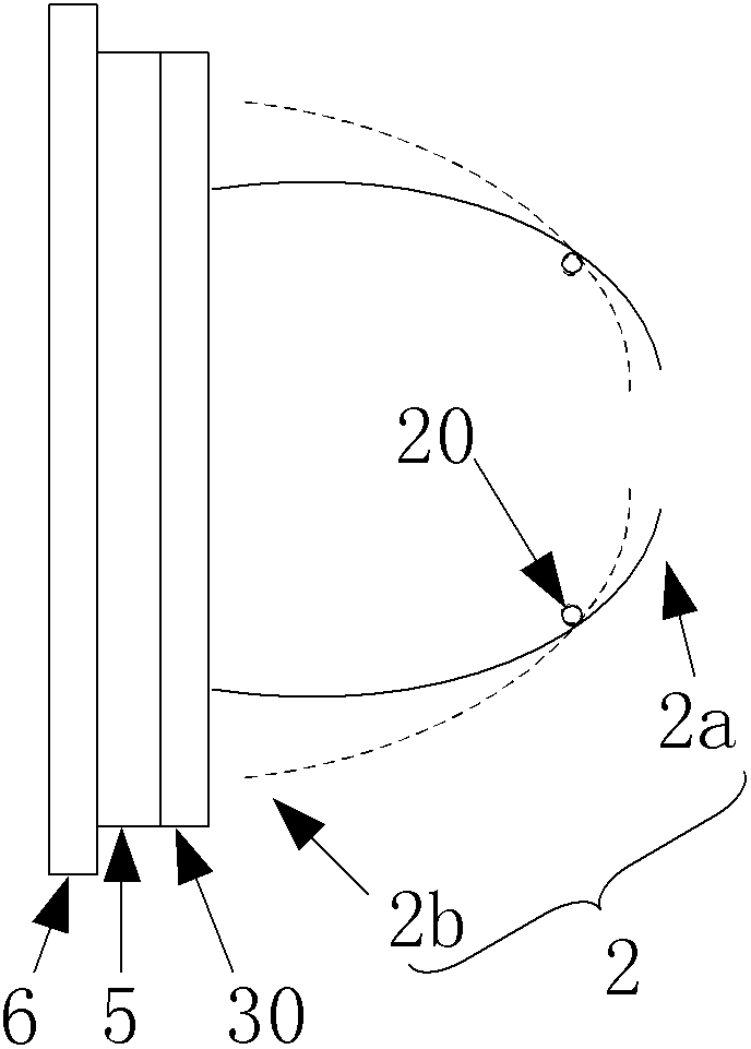
[0045] see image 3 , the automatic compensating clutch of the present invention comprises:

[0046] ——The housing 1 is in the shape of an inverted bowl and is fixed on the flywheel 6 , forming a first cavity between the housing 1 and the flywheel 6 . On the upper side 11 of the housing 1 there is a hole 111 .

[0047] - The diaphragm spring 2 is disc-shaped and located in the first cavity. The pressure-receiving end 2a of the diaphragm spring 2 protrudes out of the hole 111 on the top surface of the casing, and is used for contacting with the release bearing. The middle part of the diaphragm spring 2 is fixed on the housing 1 . The other end 2b of the diaphragm spring 2 is connected to the auxiliary pressure plate 3 . The diaphragm spring 2 is equivalent to a lever, and when its pressure receiving end 2a is pressed down, its other end 2b will be lifted toward the top surface 11 of the housing.

[0048] - The auxiliary pressure plate 3 is in the shape of an inverted cylin...


PUM


Abstract

Disclosed are an automatic complementary clutch and a realization method therefor. The automatic complementary clutch comprises a housing (1), a diaphragm spring (2), secondary pressure disks (3), a primary pressure disk (4), friction disks (5), a roller chassis (7), a roller (8), a roller top disk (9) and a roller return spring (90). When the diaphragm spring (2) and the secondary pressure disks (3) undergo an external force, the secondary pressure disks (3) on both sides of the roller (8) and the primary pressure disk (4) form a spatial shape wide at the top and narrow at the bottom to deal with the process of the clutch being depressed or released. The automatic complementary clutch is able to solve efficiently the problem of change when the clutch is depressed, caused by wearing of the friction disk ubiquitous in an ordinary dry-type friction clutch, and the problem of change in the separation force due to change in the diaphragm spring characteristic curve, such that the clutch is able to keep uniform properties during the whole of the service life thereof.

Description

technical field [0001] The invention relates to a clutch of an automobile. Background technique [0002] The clutch is located between the engine and gearbox of the car, and is usually installed together with the flywheel of the engine crankshaft. The output shaft of the clutch is the input shaft of the gearbox. During the process of the car from starting to running, the driver can step on or release the clutch pedal as required to separate or engage the engine and the gearbox, so as to cut off or transmit the power input from the engine to the gearbox. [0003] According to different torque transmission methods, automobile clutches are divided into friction clutches, electromagnetic clutches, and hydraulic couplings, among which friction clutches are divided into dry type and wet type. [0004] Dry friction clutches are commonly used in manual transmissions (MT for short), automatic mechanical transmissions (AMT for short) and dual clutch transmissions (DCT for short). ...

Claims


Application Information

Patent Timeline
Patent Type & Authority Patents(China)
IPC IPC(8): F16D13/50F16D13/75
CPCF16D13/757F16D13/71
Inventor 于明涛
Owner UNITED AUTOMOTIVE ELECTRONICS SYST
Why Eureka
Try Eureka