Power circuit of field effect tube microwave amplifier

A microwave amplifier and field effect tube technology, which is used in improving amplifiers to reduce temperature/power supply voltage changes, high-frequency amplifiers, etc., can solve problems such as increasing costs, and achieve the effect of preventing burnout and simplifying the process of bias debugging.

Inactive Publication Date: 2007-09-12
上海杰盛无线通讯设备有限公司
View PDF0 Cites 10 Cited by
  • Summary
  • Abstract
  • Description
  • Claims
  • Application Information

AI Technical Summary

Problems solved by technology

If the bias circuit is readjusted for each batch of FETs, it will obviously increase the cost of R&D and production

Method used


Image

  • Power circuit of field effect tube microwave amplifier

Examples


Embodiment Construction

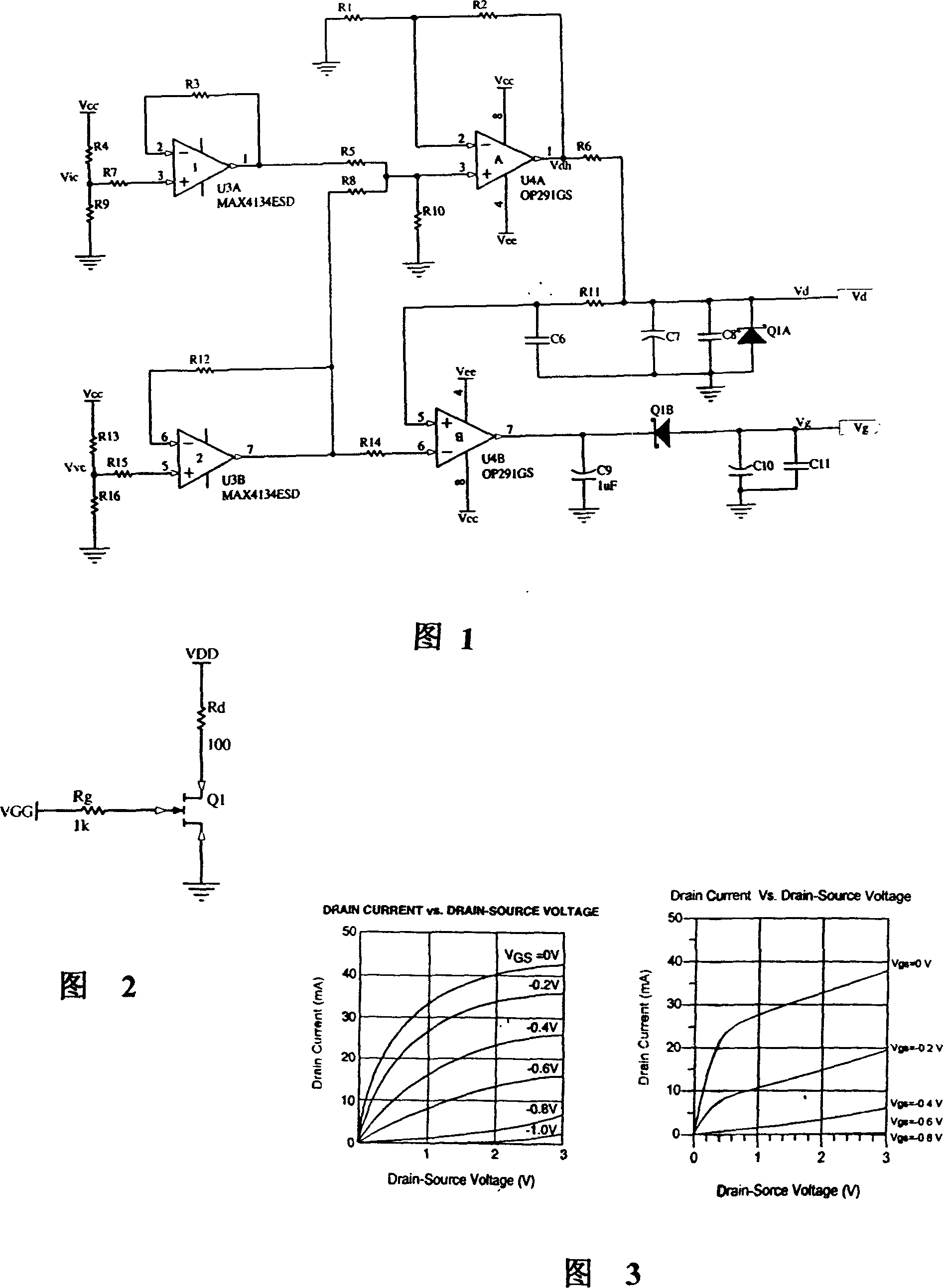
[0010] Please refer to FIG. 1 , which is a schematic diagram of a closed-loop current control FET DC bias, wherein the port Vd is connected to the drain of the FET; the port Vg is connected to the gate of the FET. Its working process is as follows:

[0011] 1. Through the voltage division of resistors R13 and R16, Vvc=VCC*R16 / (R13+R16) can be obtained, and Vd≈Vvc can be obtained through U3 and U4B, that is, the drain voltage is completely determined by R13 and R16, and has nothing to do with the drain current.

[0012] 2. Get Vic=VCC*R9 / (R4+R9) through the voltage division of resistors R4 and R9, first pass through the follower U3B, and add Vvc through the adder U4A (set R1=R10, R2=R5+R8), that is Vdh≈Vvc+Vic. The drain current of the FET is equal to the current flowing through R6, that is, Id=(Vdh-Vd) / R6≈Vic / R6.

[0013] The drain current of this FET is determined by R4, R9 and R6. Since the current limiting resistor R6 is reserved, the maximum drain current Id max=Vdh / R6 ...


PUM


Abstract

The invention provides a field effect tube microwave amplifier power circuit, the electric circuit uses closed loop operational amplifier U3A, U4A and U3B, U4B, the U3B synchronism input end, which obtains by the resistance differential pressure, its opposition input end delivers to the U4A synchronism input end after through the resistance, the U4A output leaks after the resistance R6 connects to the field effect tube drain electrode, as drain electrode voltage; the U3A synchronism input end also obtains by the resistance differential pressure, its output delivers to the U4B opposition input end after through the resistance, the U4B output, after the isolating diode and connect the field effect tube grid, as grid voltage. The invention advantage is, the closed loop electric current controlled FET DC biasing circuit separately through certain resistance value set the drain electrode voltage and current, enables different FET to obtain same drain electrode voltage and current under the same biaing circuit, thus guarantees the consistent characteristic when the FET works.

Description

technical field [0001] The invention relates to a field effect tube microwave amplifier power supply circuit. Background technique [0002] In microwave receiver design, in order to improve the sensitivity of the receiver, a low noise amplifier (LNA) is generally used in the front stage. At present, there are not many commercial microwave integrated circuits covering the C-band and above, and the price is high, and there is still much room for improvement in performance. Field effect (FET) tubes, including metal-semiconductor field effect tubes (MESFET) and high-electronic Mobility Field Effect Transistor (HEMT) amplifier performance and price are more advantageous than the former. However, due to the large discreteness of the FET tube, the consistency of the product is poor. [0003] Figure 3 shows the drain current-voltage curve cluster of a typical FET (Eunyda's FHX35LG), which shows that the drain current IDS can be seen as a function of the gate voltage VGS and the dr...

Claims


Application Information

Patent Timeline
Patent Type & Authority Applications(China)
IPC IPC(8): H03F1/30H03F3/189
Inventor 陈松麟张勇
Owner 上海杰盛无线通讯设备有限公司
Why Eureka
Try Eureka