
Tensioning means

A tensioning device and pre-tensioning technology, applied in the direction of transmission devices, belts/chains/gears, mechanical equipment, etc., can solve the problems of large structural space, increased size of tensioning devices, etc., and achieve the effect of weight saving

Inactive Publication Date: 2012-07-04
SCHAEFFLER TECH AG & CO KG
View PDF5 Cites 4 Cited by
  • Summary
  • Abstract
  • Description
  • Claims
  • Application Information

AI Technical Summary

Problems solved by technology

The known leaf springs for the tensioning device require a large amount of construction space due to their size, whereby the overall size of the tensioning device increases correspondingly

Method used


Image

  • Tensioning means
  • Tensioning means
  • Tensioning means

Examples


Embodiment Construction

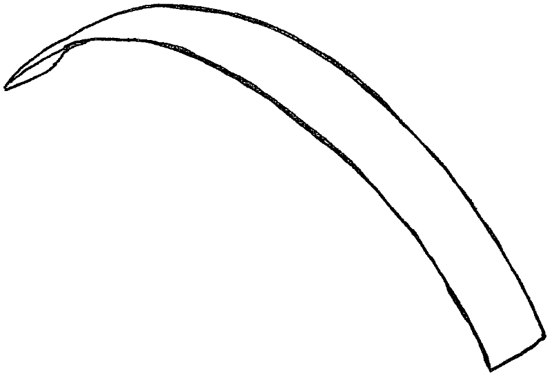
[0015] FIG. 1 shows a leaf spring known, for example, from laid-open publication DE 11 2006 001 473 T5. The leaf spring is rectangular and prebent in the shape of a bow. In the installed state, the leaf spring is deformed in an opposite bow-shape and thus exerts a pretensioning force on the tensioning rail.

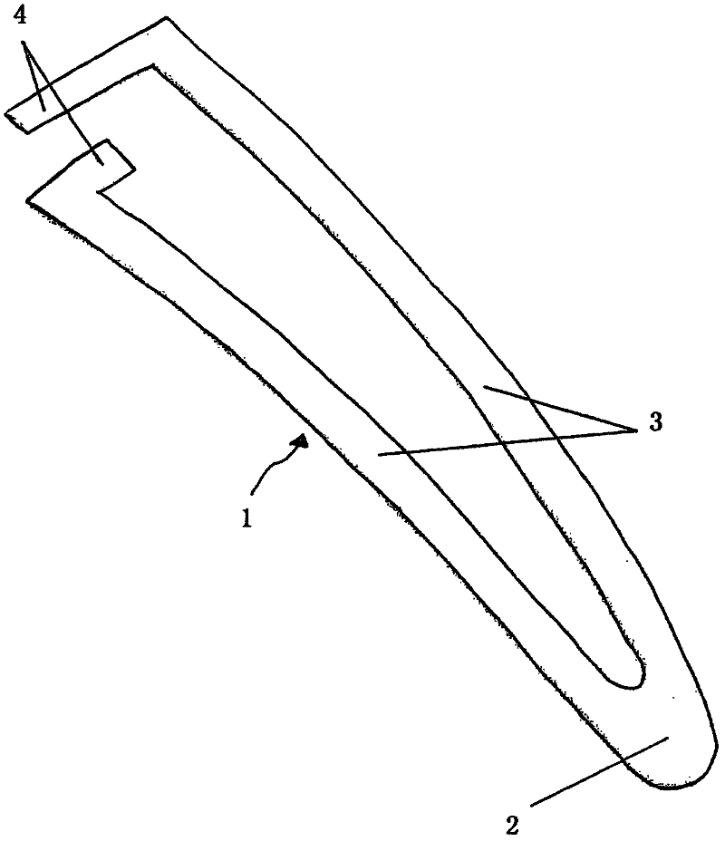
[0016] exist figure 2 A double-armed leaf spring 1 according to the invention is shown in . The two arms 3 of the leaf spring 1 each have a suspension point 4 . The suspension points 4 form end sections of the arms 3 and are substantially at right angles to the arms 3 , wherein the suspension points are each oriented in the direction of the other arm 3 . The suspension points 4 are arranged offset from one another and thus have different distances from the base section 2 of the connecting arm 3 .

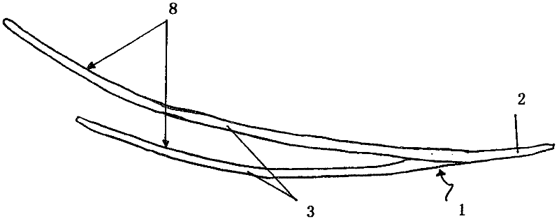
[0017] exist image 3 can be seen in side view from figure 2 It can be seen in this view of the leaf spring 1 that the arms 3 have different radii of curvature 8 and diff...


PUM


Abstract

A tensioning means for tensioning an endless traction means in an engine of a vehicle. The tensioning means having a leaf spring 1 which is arranged between a vehicle mounted locating face and a tensioning rail. The leaf spring 1 is installed in a pre-tensioned position and the leaf spring 1 is formed with two arms.

Description

technical field [0001] The invention relates to a tensioning device according to the preamble of claim 1 . Background technique [0002] In a force transmission mechanism configured to transmit the rotational motion of the crankshaft to one or more camshafts or other components of a vehicle's internal combustion engine by means of endless traction, such as a chain, the stress on the endless traction mechanism is maintained constant by, The method is: set a tensioning device that applies tension to the endless traction mechanism. The tensioning force transmitted to the endless traction mechanism, for example via a tensioning rail, can be provided, for example, by means of a leaf spring. Such a tensioning device with a leaf spring is known from DE 11 2006 001 473 T5, wherein the leaf spring is embodied here in a rectangular shape and is pre-deformed in a bow shape, so that the leaf spring is deformed opposite to the bow shape during assembly, And thus apply a pretensioning f...

Claims


Application Information

Patent Timeline
Patent Type & Authority Applications(China)
IPC IPC(8): F16H7/08
CPCF16H7/08F16H2007/0804F16H2007/0893
Inventor 彼得·蒂罗勒
Owner SCHAEFFLER TECH AG & CO KG
Learn More