
Double decompression protection device for quick hot water faucet

A hot water faucet and protection device technology, applied in the direction of valve heating/cooling device, valve device, function valve type, etc., can solve problems such as heat rise, faucet steam pressure explosion, etc.

Active Publication Date: 2013-06-05
浙江普瑞圣工贸有限公司
View PDF8 Cites 1 Cited by
  • Summary
  • Abstract
  • Description
  • Claims
  • Application Information

AI Technical Summary

Problems solved by technology

The existing instant hot water faucet in this aspect only has a single leakage or overvoltage and overheating protection device inside. When the temperature is low in winter, the water in the pipeline freezes and other factors, the internal protection device is damaged, and the faucet still works normally. , the heat rises sharply in the faucet, and the steam pressure in the faucet will cause explosion and other safety hazards

Method used


Image

  • Double decompression protection device for quick hot water faucet
  • Double decompression protection device for quick hot water faucet
  • Double decompression protection device for quick hot water faucet

Examples


Embodiment 1

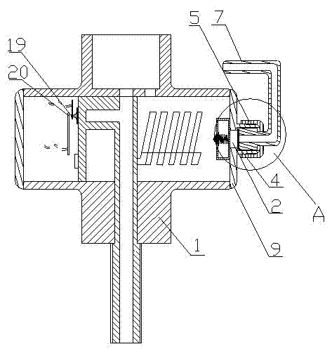
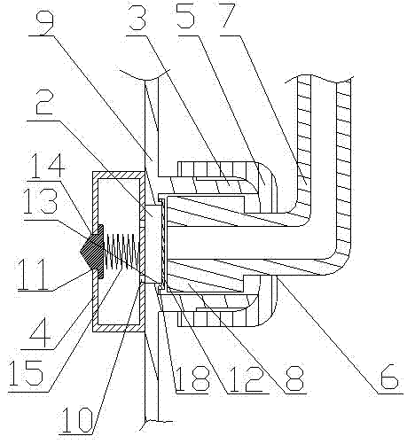
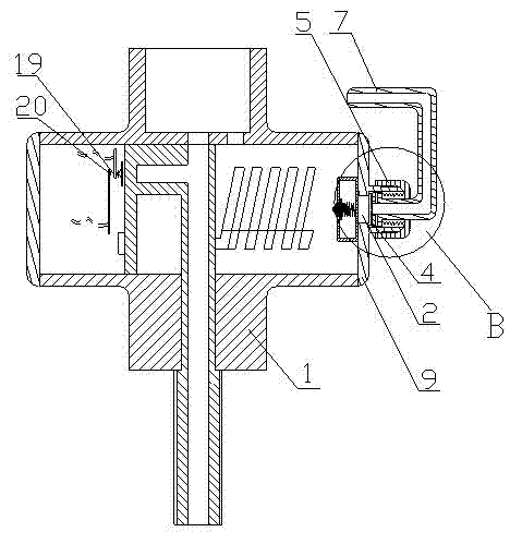
[0016] Embodiment 1: A double pressure relief protection device for an instant hot water faucet, including an end cap 9 at one end of the faucet body 1; the end cap 9 is provided with a round hole a2; the outer side of the round hole a2 is provided with a pressure relief The membrane 12 is fixed with a pressure relief block 4 with a hollow box structure inside; the contact wall between the pressure relief block 4 and the end cover 9 is provided with a hole 10 communicating with the round hole a2, which is opposite to the end cover 9 The side wall is provided with a hole b11; the hole b11 is equipped with a thimble 14; the thimble 14 seals the hole b11 from the inside to the outside through the spring a15; the circular hole a2 protrudes outward to form a boss 13; the leak The pressure film 12 is buckled on the boss 13 through the inner convex block (18) on its edge.

[0017] During use, first power on the faucet, the faucet works normally, and is protected by the first layer of...

Embodiment 2

[0018] Embodiment 2: A dual pressure relief protection device for instant hot water faucets, including an end cap 9 at one end of the faucet body 1; a circular hole a2 is provided on the end cap 9; a pressure relief device is provided outside the circular hole a2 The membrane 12 is fixed with a pressure relief block 4 with a hollow box structure inside; the contact wall between the pressure relief block 4 and the end cover 9 is provided with a hole 10 communicating with the round hole a2, which is opposite to the end cover 9 The side wall is provided with a hole b11; the hole b11 is equipped with a thimble 14; the thimble 14 seals the hole b11 from inside to outside through a spring a15. On the end cover 9 concentric with the circular hole a2 is provided with a cylindrical block 3 protruding outward; the cylindrical block 3 is equipped with a nut 5; the nut 5 is provided with a circular hole b6; inside the cylindrical block 3 A chuck 8 is provided; the left side of the chuck 8...


PUM


Abstract

The invention relates to a decompression protection device, in particular to a double decompression protection device for a quick hot water faucet, which comprises an end cover at one end of a faucet body. A round hole a is arranged on the end cover, a decompression file is positioned on the outer side of the round hole a, a decompression block of a hollow box-body structure is fixedly arranged on the inner side of the round hole a, a contact wall between the decompression block and the end cover is provided with a hole communicated with the round hole a, the other wall is provided with a hole b, a thimble is arranged in the hole b, and the hole b is sealed from the inside to the outside through the spring. The decompression protection device is ingeniously provided with the decompressionblock of the hollow box-body structure and the decompression film. Steam can be exhausted out of the faucet under impact of steam pressure in the faucet through the decompression block and the decompression film, thereby avoiding explosion caused by steam pressure in the faucet.

Description

technical field [0001] The invention relates to a pressure relief protection device, in particular to a double pressure relief protection device for an instant hot water faucet. Background technique [0002] Now as people's living standards are getting better and better, the use of various devices is becoming more and more convenient. In the cold winter, when you turn on the tap, you can get hot water in a short time. This kind of convenience can only be realized by using water heaters and solar energy in the past, which brings great inconvenience to installation and pipe connections. Now there are new fast-heating faucets on the market, and most of them heat the tube in a short period of time by energizing to achieve the fast-heating effect. The existing instant hot water faucet in this aspect only has a single leakage or overvoltage and overheating protection device inside. When the temperature is low in winter, the water in the pipeline freezes and other factors, the int...

Claims


Application Information

Patent Timeline
Patent Type & Authority Patents(China)
IPC IPC(8): F16K49/00F16K17/04
Inventor 钭子奇
Owner 浙江普瑞圣工贸有限公司
Learn More