Shaped charge tubing cutter

a cutter and shaped charge technology, applied in the direction of explosive charges, aerial display rockets, borehole/well accessories, etc., can solve the problems of inability to accurately determine the effect of elevated pressure and temperature on sc performance, inability to accurately determine the effect of elevated pressure and temperature, and inability to accurately determine the effect of sc performan

Inactive Publication Date: 2006-07-11
HUNTING TITAN
View PDF17 Cites 33 Cited by
  • Summary
  • Abstract
  • Description
  • Claims
  • Application Information

AI Technical Summary

Benefits of technology

[0027]Externally, the SC housing is formed to an axially projecting salient for secure attachment of a centralizer having spring steel centralizing blades whereby the blades have significant abrasion resistance and are free to flex without exceeding material yield limits.
[0029]A cylindrical aperture is formed along the explosive unit axis to receive a detonation booster comprising a substantially cylindrical brass casement having an elongated, small diameter axial primer channel into a large diameter main cavity. High explosive powder in the primer chann l is packed to a density of about 1.1 to about 1.2 g / cc whereas the main cavity explosive is packed to about 1.5 to about 1.6 g / cc. Axially opposite of the prim r channel entry into the main cavity, the main cavity is volume defined by a brass plug insert. The detonation booster casement is positioned along the axial aperture to locate the juncture plane of the apex truncations across the approximate center of the booster main cavity. The booster casement wall thickness along the length of the primer channel is sized to prevent detonation of the SC explosive by the primer decomposition.

Problems solved by technology

Although simple, fast and inexpensive, SC cutters are reputedly not the most reliable means for cutting tubing downhole.
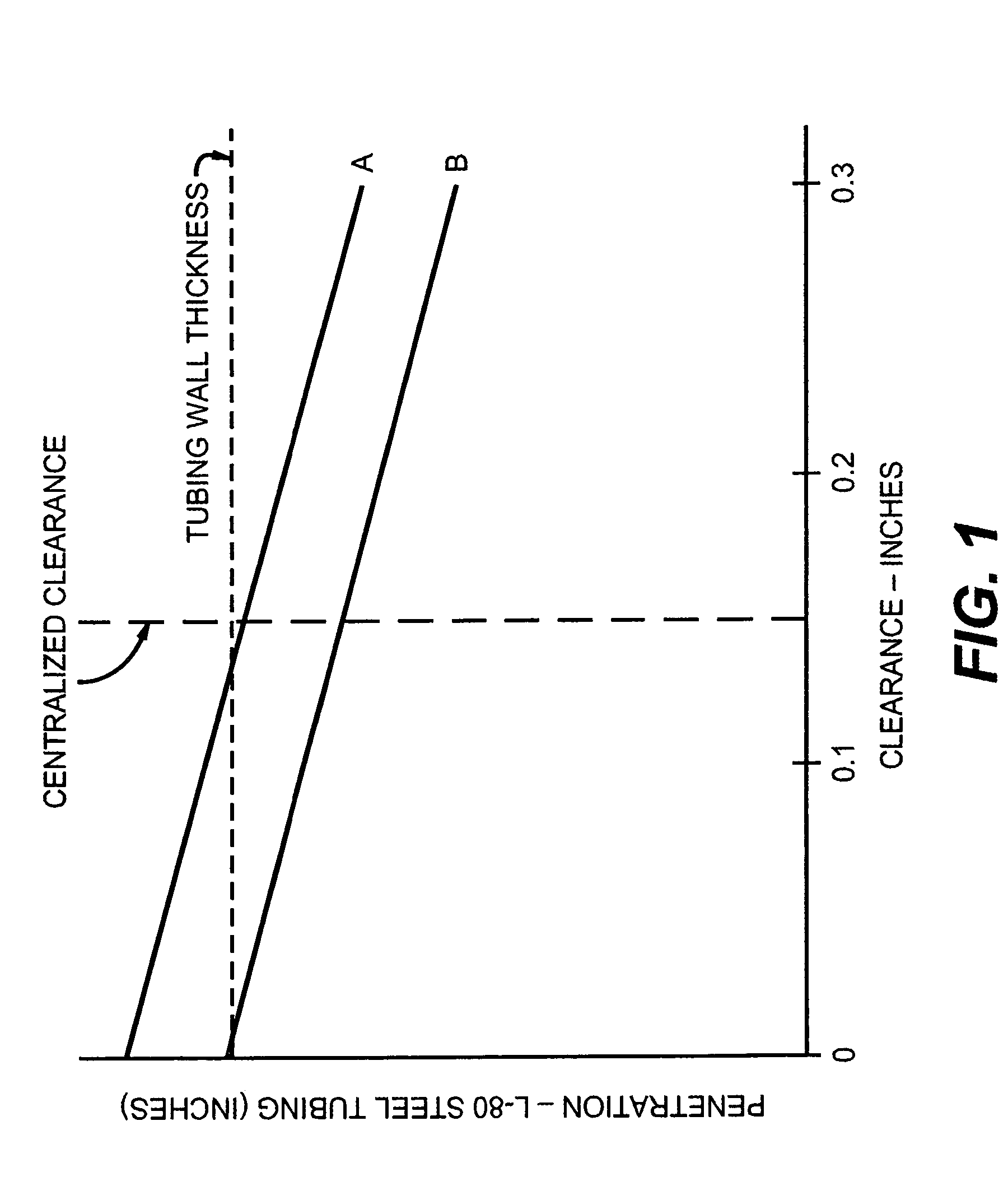
In field use, however, downhole well conditions may exceed 10,000 psi and 400° F. The impact of such elevated pressur and temperature has upon SC performance, generally, is not well understood.
However, such prior art centralizers are constructed of plastic or other low abrasion resistive material.
Hence, such prior art centralizers are frequently damaged while running into a well by abrasion or by various restriction elements within the tubing bore.
As the data of FIG. 1 indicates, the penetration capacity of most cutters is marginal under optimum conditions and substantially lacking under severe conditions.
Another finding from test experiences is that SC cutters frequently lose penetrating capability when the cutter is mounted rigidly against the top sub of the tubing assembly or against the bottom of the SC cutter housing.
The loss of cutting capacity is most severe when the SC is tightly coupled only on one side of the SC cutter.
Such disruption of the normal jet formation also increases an undesirable flared distortion of the severed tubing wall at the separation plane and an undesirable deformation to the end face of the top sub.
I have discovered that if a portion of that gas escapes into the jet cavity between the conical liners in advance of the liner material merger, the intensity and direction of the cutting jet is compromised.

Method used


Image

  • Shaped charge tubing cutter
  • Shaped charge tubing cutter
  • Shaped charge tubing cutter

Examples


Embodiment Construction

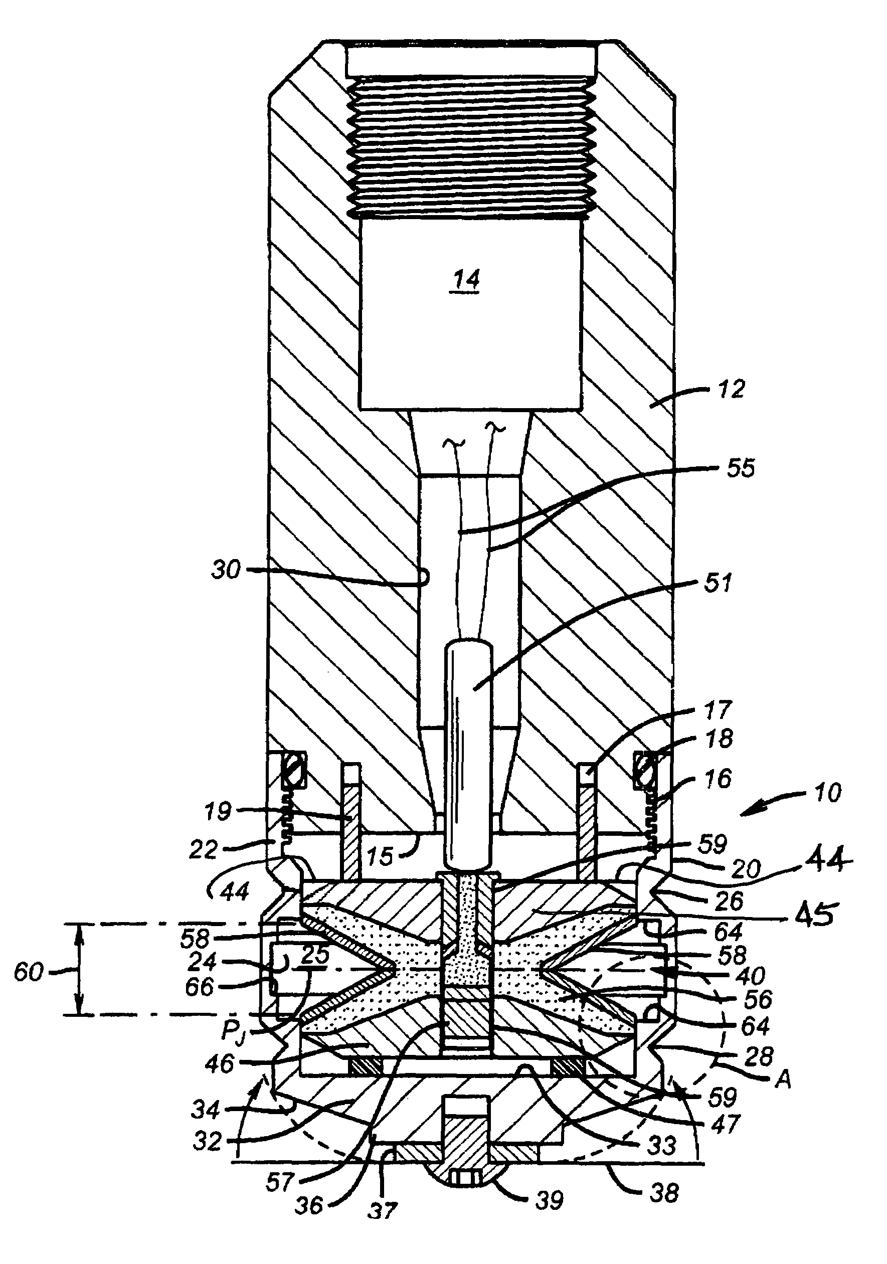
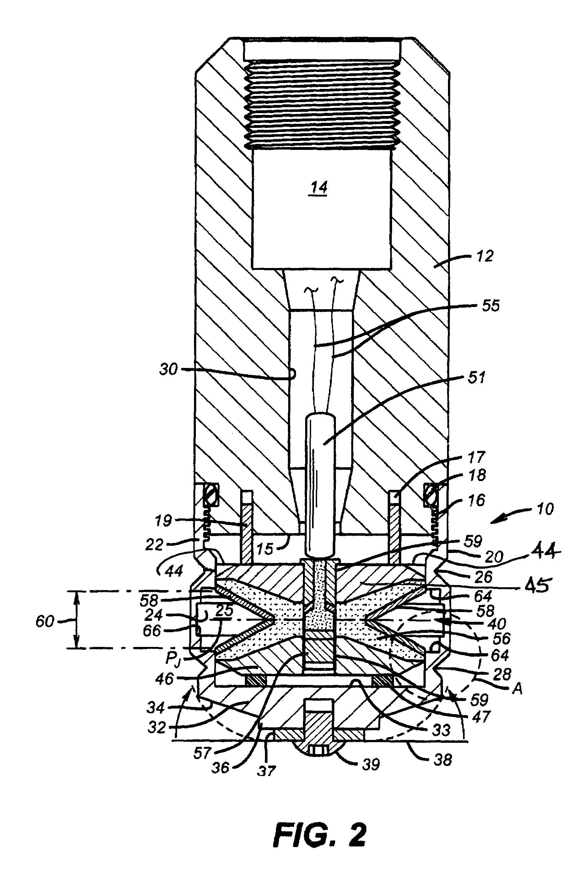
[0044]Referring initially to the invention embodiment of FIG. 2, the cutter assembly 10 comprises a top sub 12 having a threaded internal socket 14 for secure assembly with an appropriate wire line or tubing suspension. In general, the cutter assembly has a substantially circular cross-section. Consequentially, the outer configuration of the cutter assembly is substantially cylindrical. The opposite end of the top sub includes a substantially flat end face 15 having dowel sockets 17 for receipt of spacer pins 19. The end face perimeter is delineated by a housing assembly thread 16 and an O-ring seal 18. The axial center of the top sub is bored between the assembly socket 14 and the end face 15 to provide a detonator socket 30.

[0045]Occasionally, when operating tubing cutters, the detonator socket 30 becomes plugged with debris from the detonator, its holder and debris from the well. Resultantly, pressure is trapped within the top sub which presents a personnel hazard when disassembl...


PUM


Abstract

A shaped charge tubing cutter includes a minimal contact suspension to isolate the cutter explosive from the housing and sub structure. A charge detonation booster main-cavity is located on the juncture of the charge truncation planes. Explosive in the booster main-cavity is detonated by a shielded primer path. Explosive density in the primer path is less than the main-cavity density. A dense, powdered metal SC liner and an abruptly stepped jet window in the tubing cutter housing improve performance. The axial span of the jet window is preferably aligned with the axial span between the liner bases. A testing apparatus and procedure inexpensively verifies downhole performance.

Description

CROSS REFERENCE TO RELATED APPLICATIONS[0001]This application is a Division of application Ser. No. 10 / 017,116, filed Dec. 14, 2001 now U.S. Pat. No. 6,644,099.STATEMENT REGARDING FEDERALLY SPONSORED RESEARCH OR DEVELOPMENT[0002]Not ApplicableBACKGROUND OF THE INVENTION[0003]1. Field of the Invention[0004]The present invention relates to shaped charge tools for cutting pipe and tubing. More particularly, the invention is directed to methods and apparatus for improving the performance and cutting reliability of shaped charge tubing cutters.[0005]2. Description of Related Art[0006]The capacity to quickly, reliably and cleanly sever a joint of tubing or casing deeply within a wellbore is an essential maintenance and salvage operation in the petroleum drilling and exploration industry. Generally, the industry relies upon mechanical, chemical or pyrotechnic devices for such cutting. Among the available options, explosive shaped charge (SC) cutters are often the simplest, fastest and leas...

Claims


Application Information

Patent Timeline
Patent Type & Authority Patents(United States)
IPC IPC(8): F42B1/00E21B29/02
CPCE21B29/02
Inventor BELL, WILLIAM T.
Owner HUNTING TITAN
Why Eureka
Try Eureka