See-saw interconnect assembly with dielectric carrier grid providing spring suspension

a dielectric carrier grid and interconnect assembly technology, applied in the direction of instruments, printed circuits, measurement devices, etc., can solve the problems of significant limitation on maximizing the deflection range and becoming increasingly difficult to design interconnect arrays, and achieve the effect of improving the tip scribing

Active Publication Date: 2006-06-13
INTERCONNECT DEVICES +2
View PDF8 Cites 39 Cited by
  • Summary
  • Abstract
  • Description
  • Claims
  • Application Information

AI Technical Summary

Benefits of technology

[0008]Each interconnect structure is fabricated and combined with the carrier grid for performing a see-saw pivoting movement around a rotation axis that substantially coincides with a symmetry plane of torsion features that are part of the resilient portions. The torsion features protrude laterally towards and adhere to a central portion of the see-saw interconnect such that an angular movement of the interconnect is resiliently opposed by the torsion feature and the remainder of the resilient portions. The resilient portions and interconnects may be independently optimized to provide the interconnects with maximum deflection stiffness, wear resistance, and conductivity.
[0011]The initial contact force of the tips may be tuned by adjusting the angle of the see-saw interconnect with respect to the approach direction of the test contacts. This may be utilized to improve the tips' scribing on the test pads.

Problems solved by technology

With decreasing contact pitches and increasing numbers of test contacts of packaged chips, it becomes increasingly challenging to design interconnect arrays that can be fabricated with low fabrication costs while meeting the demand for maximum deflection with an ever decreasing footprint available for each interconnect stage.
This poses a significant limitation on maximizing deflection range due to the opposing material requirements for stiffness of the contacting features and resilience of the spring features.

Method used


Image

  • See-saw interconnect assembly with dielectric carrier grid providing spring suspension
  • See-saw interconnect assembly with dielectric carrier grid providing spring suspension
  • See-saw interconnect assembly with dielectric carrier grid providing spring suspension

Examples


Embodiment Construction

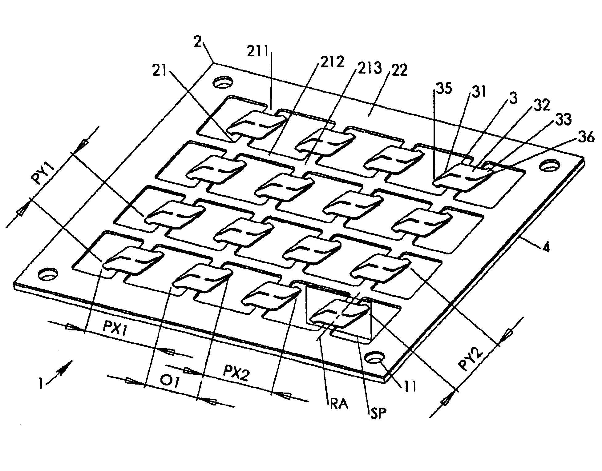
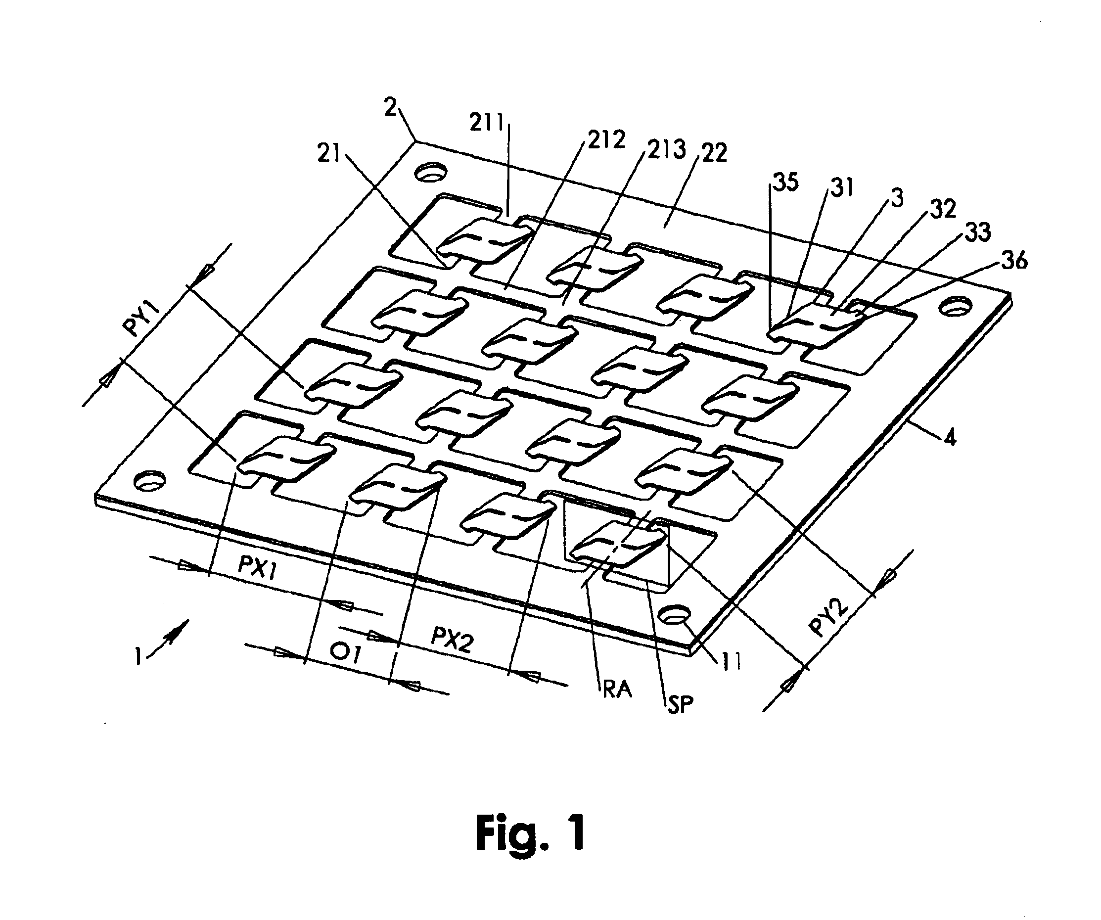
[0024]In the following the terms “horizontal, vertical, upwards, downwards, bottom, top, X-oriented, Y-oriented” are used in conjunction with the Figures. As it may be clear to anyone skilled in the art, these terms are used solely for the purpose of ease of understanding and to describe spatial relations of elements with respect to each other.

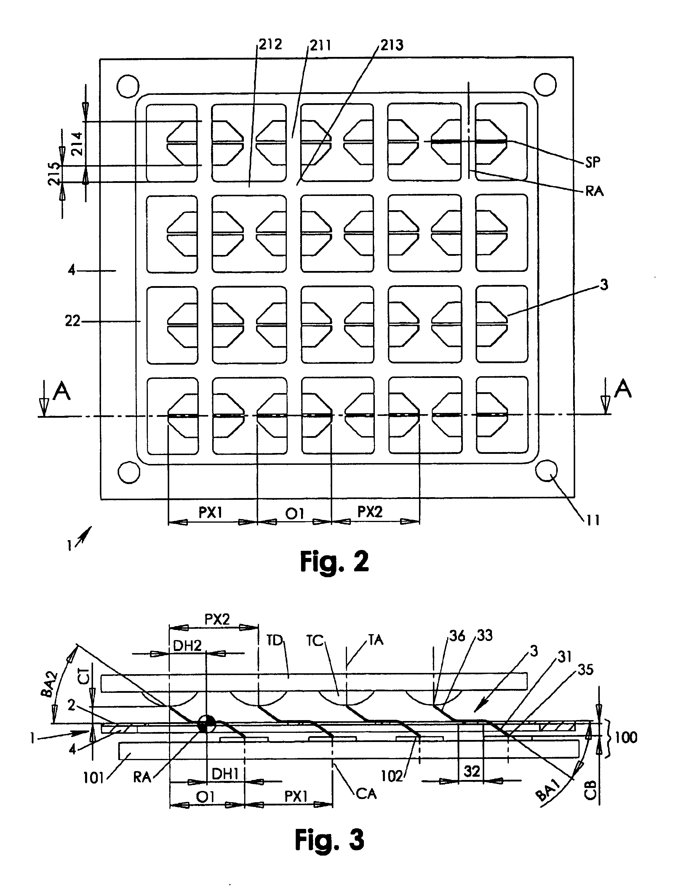
[0025]FIGS. 1, 2 show an interconnect assembly 1 that includes a horizontal dielectric film 2 circumferentially adhering to a support frame 4 via a grid flange 22. Shaped in the dielectric film 2 is a carrier grid 21, which may have X-oriented grid members 212 and Y-oriented grid members 211 that connect in the grid nodes 213. On centered locations of the Y-oriented grid members 211 adhere electrically conductive see-saw structures 3. Preferably each of the see saw structures 3 has a planar central portion 32 that overlaps with an interface portion 214 of the grid members 211. The see-saw structures 3 are connected to the carrier grid 21 via t...


PUM


Abstract

An interconnect assembly includes a number of interconnects combined in a preferably planar dielectric carrier frame having resilient portions acting as spring members in conjunction with their respective interconnect's rotational displacement during operational contacting. Each interconnect is fabricated as a see-saw structure pivoting around a rotation axis that substantially coincides with a symmetry plane of the torsion features provided by the resilient portion. The torsion features protrude towards and adhere to a central portion of the see-saw interconnect such that an angular movement of the interconnect is resiliently opposed by the torsion feature and the resilient portion. The torsion features and interconnects may be independently optimized to provide the interconnect with maximum stiffness and a maximum deflection at same time.

Description

FIELD OF INVENTION[0001]The present invention relates to Interconnect assemblies for repetitively establishing conductive contact between opposing contact arrays. Particularly, the present invention relates to interconnect assemblies having a number of arrayed interconnect stages including see-saw interconnects embedded in a spring force providing dielectric carrier structure.BACKGROUND OF INVENTION[0002]Demand for ever decreasing chip fabrication costs forces the industry to develop new solutions for inexpensive and reliable chip testing devices. A common component for repetitively contacting contact arrays of tested circuit chips is an interconnect assembly that is placed adjacent a test apparatus contact array that has contact pitch corresponding to the tested chips' carrier (package) contact pitch. During packaged chip testing, a package is brought with its contact array into contact with the interconnect assembly such that an independent conductive contact is established betwee...

Claims


Application Information

Patent Timeline
Patent Type & Authority Patents(United States)
IPC IPC(8): H01R12/00G01R1/067G01R1/073G01R3/00
CPCG01R1/06711G01R3/00G01R1/07307
Inventor KISTER, JANUARYJAQUETTE, JAMESTOKRAKS, GENE
Owner INTERCONNECT DEVICES
Why Eureka
Try Eureka