Vehicle and structure shield

a shielding and armor technology, applied in the direction of shields, protective equipment, transportation and packaging, etc., can solve the problems of high cost, high installation cost, and high cost of armor equipped vehicles, and achieve low vehicle signature, easy installation and removal, and easy adaptability

Active Publication Date: 2011-09-06
FOSTER-MILLER
View PDF115 Cites 33 Cited by
  • Summary
  • Abstract
  • Description
  • Claims
  • Application Information

AI Technical Summary

Benefits of technology

[0014]In accordance with one aspect of the subject invention, a new vehicle and structure shield is provided which, in one specific version, is inexpensive, lightweight, easy to install and remove (even in the field), easy to adapt to a variety of platforms, effective, and exhibits a low vehicle signature. Various other embodiments are within the scope of the subject invention.
[0015]The subject invention results from the realization, in part, that a new vehicle and structure shield, in one specific example, features a plurality of spaced rods held in position via the nodes of a net and used to dud an RPG or other threat allowing the frame for the net to be lightweight and inexpensive and also easily attached to and removed from a vehicle or structure.
[0021]One shield system in accordance with the subject invention features a flexible net including cords intersecting at nodes, a hard point for at least select nodes, a frame including mounting brackets positioning the frame in a spaced relationship with a vehicle or structure, a first releasable fastener subsystem releasably securing the net to the frame, and a second releasable fastener subsystem releasably securing the mounting brackets of the frame to the vehicle or structure. The cords of the net are configured with compliance which prevents detonation of an RPG striking a cord.

Problems solved by technology

Static armor such as shown in U.S. Pat. Nos. 5,170,690; 5,191,166; 5,333,532; 4,928,575; and WO 2006 / 134,407 is often heavy and time consuming to install.
When a significant amount of weight is added to a HMMWV, for example, it can become difficult to maneuver and top heavy.
Such an armor equipped vehicle also burns an excessive amount of fuel.
Moreover, known static systems do not prevent detonation of the RPG.
But, bar / slat armor is also very heavy.
Often, a vehicle designed to be carried by a specific class of aircraft cannot be carried when outfitted with bar / slat armor.
Also, if the bar / slat armor is hit with a strike, the RPG still detonates.
Bar / slat armor, if damaged, can block doors, windows, and access hatches of a vehicle.
The chain link fencing, however, is not sufficiently compliant to prevent detonation of an RPG if it strikes the fencing material.
Chain like fencing, although lighter than bar / slat armor, is still fairly heavy.
Despite the technology described in the above prior art, Rocket Propelled Grenades (RPGs) and other threats used by enemy forces and insurgents remain a serious threat to troops on the battlefield, on city streets, and on country roads.
RPGs pose a persistent deadly threat to moving ground vehicles and stationary structures such as security check points.
Heavily armored, lightly armored, and unarmored vehicles have been proven vulnerable to the RPG shaped charge.
Today, the RPG threat in Iraq is present at every turn and caches have been found under bridges, in pickup trucks, buried by the road sides, and even in churches.
Armor plating on a vehicle does not always protect the occupants in the case of an RPG impact and no known countermeasure has proven effective.
Systems designed to intercept and destroy an incoming threat are ineffective and / or expensive, complex, and unreliable.

Method used


Image

  • Vehicle and structure shield
  • Vehicle and structure shield
  • Vehicle and structure shield

Examples


Embodiment Construction

[0037]Aside from the preferred embodiment or embodiments disclosed below, this invention is capable of other embodiments and of being practiced or being carried out in various ways. Thus, it is to be understood that the invention is not limited in its application to the details of construction and the arrangements of components set forth in the following description or illustrated in the drawings. If only one embodiment is described herein, the claims hereof are not to be limited to that embodiment. Moreover, the claims hereof are not to be read restrictively unless there is clear and convincing evidence manifesting a certain exclusion, restriction, or disclaimer.

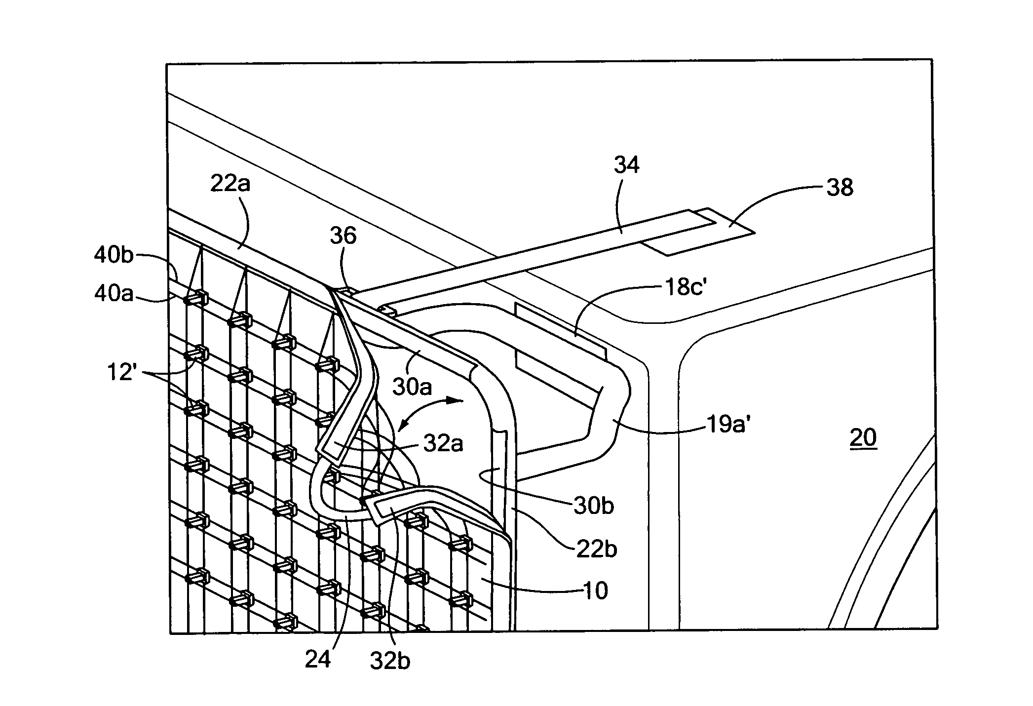
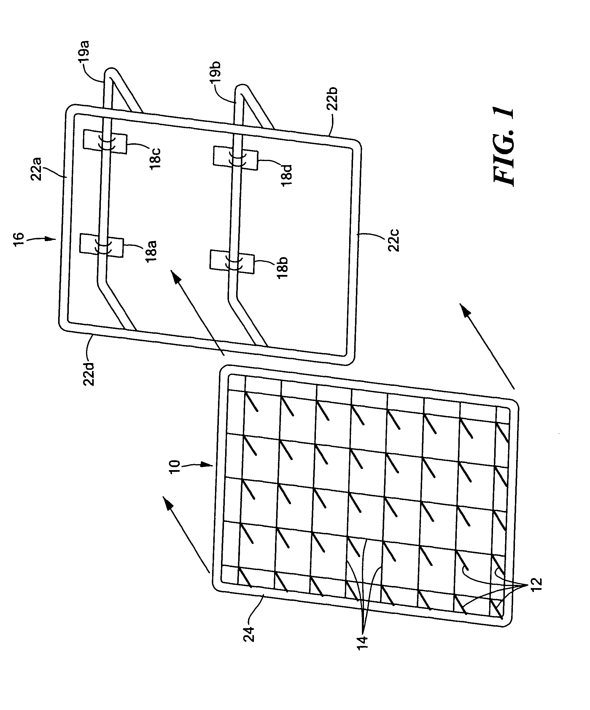
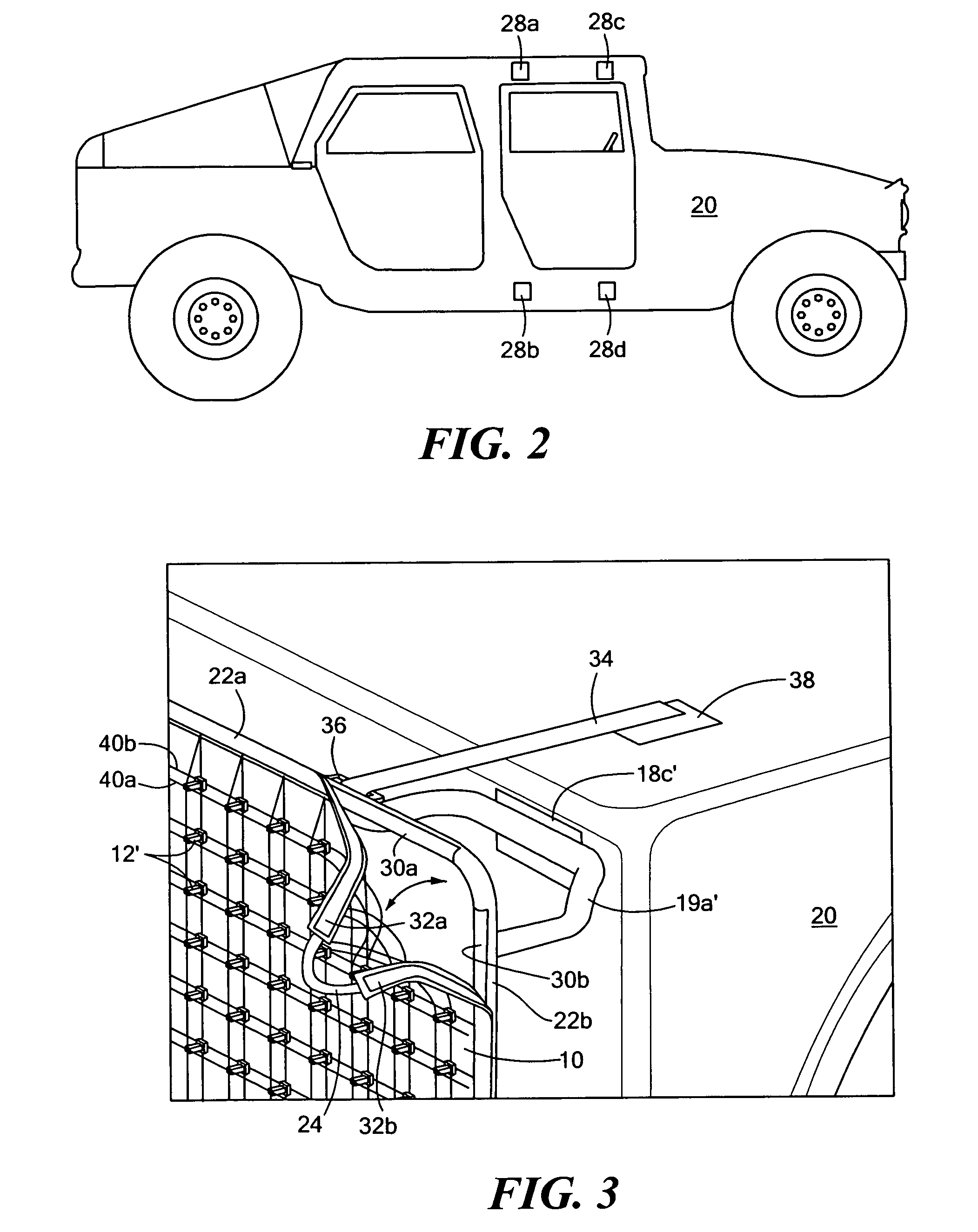
[0038]FIG. 1 shows an example of flexible net subsystem 10 and including an array of rods 12 configured to impact a projectile (e.g., the nose of an RPG) striking net 14. Frame 16 includes mounting brackets 18a-18d attached to rearwardly extending members 19a and 19b. The function of frame 16 and net 14 is to position rods ...


PUM


Abstract

A vehicle and structure shield includes a flexible net subsystem including an array of rods or hard points supported by the net subsystem and configured to impact a projectile striking the net. A frame includes mounting brackets attached thereto positioning the frame in a spaced relationship with respect to the vehicle or structure. A first releasable fastener subsystem releasably secures the net subsystem to the frame and a second releasable fastener subsystem releasably secures the mounting brackets of the frame to a vehicle or structure.

Description

RELATED APPLICATIONS[0001]This application hereby claims the benefit of and priority to U.S. Provisional Application Ser. No. 61 / 124,428, filed on Apr. 16, 2008 under 35 U.S.C. §§119, 120, 363, 365, and 37 C.F.R. §1.55 and §1.78.FIELD OF THE INVENTION[0002]The subject invention relates to ordinance shielding.BACKGROUND OF THE INVENTION[0003]Rocket propelled grenades (RPGs) and other ordinance are used by terrorist groups to target military vehicles and structures. See WO 2006 / 134407 incorporated herein by this reference.[0004]Others skilled in the art have designed intercept vehicles which deploy a net or a structure in the path of an RPG in an attempt to change its trajectory. See U.S. Pat. Nos. 7,190,304; 6,957,602; 5,578,784; and 7,328,644 all incorporated herein by this reference. Related prior art discloses the idea of deploying an airbag (U.S. Pat. No. 6,029,558) or a barrier (U.S. Pat. No. 6,279,499) in the trajectory path of a munition to deflect it. These references are als...

Claims


Application Information

Patent Timeline
Patent Type & Authority Patents(United States)
IPC IPC(8): F41H11/00F41H13/00
CPCF41H5/026F41H5/013
Inventor FARINELLA, MICHAEL D.CARDENAS, ROBERT LEELAWSON, WILLIAM R.LABRECQUE, BRENDANRUSH, FRANCESHOADLEY, DAVIDWHEATON, MICHAELANDERSON, MICHAELMANN, THOMASKANAAN, ABEDCALLAHAN, PATRICK
Owner FOSTER-MILLER
Why Eureka
Try Eureka