Illuminating device
A technology of lighting device and light guide body, applied in the field of light guide body, can solve the problems of inability to present diversified lighting effects, unfavorable development of lighting fixtures, monotonous lighting effect, etc.
- Summary
- Abstract
- Description
- Claims
- Application Information
AI Technical Summary
Problems solved by technology
Method used
Image
Examples
no. 1 example
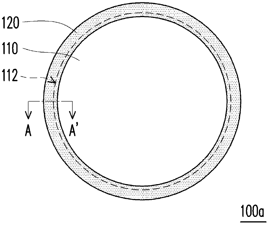
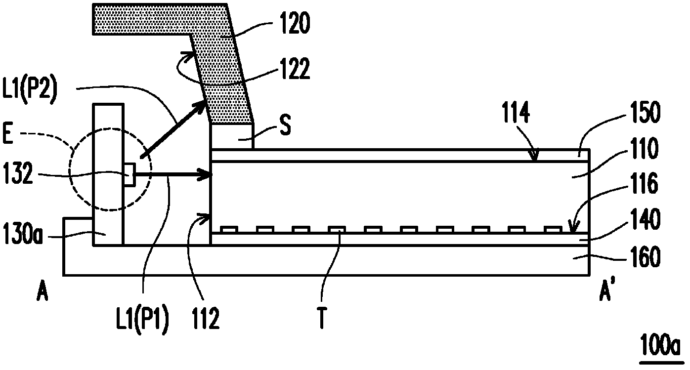
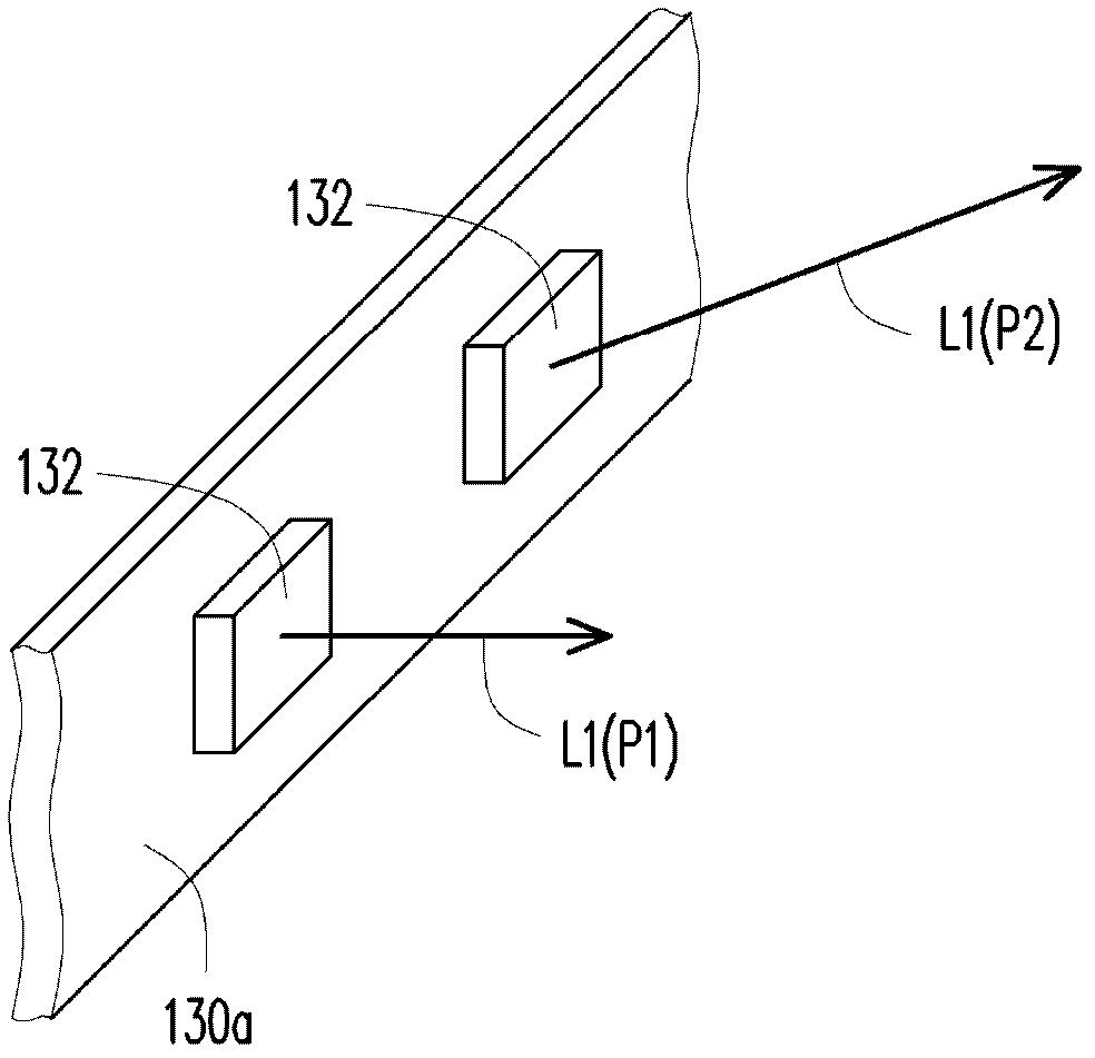
[0035] Figure 1A It is a schematic top view of the lighting device according to the first embodiment of the present invention. Figure 1B for along Figure 1A The cross-sectional schematic diagram of the section line A-A'. Figure 1C for Figure 1B The three-dimensional side view of the part circled E in the direction perpendicular to the paper surface shows an example of the arrangement of the first light emitting unit 132 of the light bar 130a.
[0036] Please refer to Figure 1A as well as Figure 1B , the lighting device 100a includes: a first light guide 110 , at least one second light guide 120 and a light bar 130a. The first light guide 110 has a first surrounding light incident surface 112 , a first light emitting surface 114 and a first light reflecting surface 116 . The first light emitting surface 114 and the first light reflecting surface 116 are adjacent to the first surrounding light incident surface 112 . The second light guide body 120 is disposed above the...
no. 2 example
[0053] Figure 2A It is a schematic top view of the lighting device according to the second embodiment of the present invention. Figure 2B for along Figure 2A The cross-sectional schematic diagram of the section line B-B'. It should be noted that, Figure 2A Only the first light guide body 110 and the second light guide body 120 are shown to clearly show the relative positions of the first light guide body 110 and the second light guide body 120 .
[0054] Please also refer to Figure 2A as well as Figure 2B , the lighting device 100b and Figure 1A and Figure 1B The illustrated lighting device 100a is substantially similar, except that in the lighting device 100b, the second light guide body 120 is disposed above the periphery of the first light guide body 110, and the edge of the second light guide body 120 is a distance from the second light guide body 110. edge of a light guide body 110, and move a certain distance D into the first light guide body 110, which is ...
no. 3 example
[0058] image 3 A schematic top view of the lighting device according to the third embodiment of the present invention is shown. Please refer to image 3 The lighting device 100c is similar to the lighting device 100a in FIG. 1 , and only a top view of the lighting device 100c is shown here.
[0059] The difference between the lighting device 100c and the lighting device 100a is that the first light guide body 110 of the lighting device 100c is a polygonal light guide plate ( image 3 shown as a rectangle), and the second light guide body 120 is a plurality of elongated light guide covers 120A˜120D, which are correspondingly arranged on each side of the polygonal light guide plate (the first light guide body 110 ). It can be noticed that the edge of the second light guide body 120 is adjacent to the edge of the first light guide body 110 .
[0060] image 3 What is shown is a rectangular first light guide body 110; however, the first light guide body 110 can be any polygon...
PUM
 Abstract
Description
Claims
Application Information
 - R&D
- Intellectual Property
- Life Sciences
- Materials
- Tech Scout
- Unparalleled Data Quality
- Higher Quality Content
- 60% Fewer Hallucinations
Browse by: Latest US Patents, China's latest patents, Technical Efficacy Thesaurus, Application Domain, Technology Topic, Popular Technical Reports.
© 2025 PatSnap. All rights reserved.Legal|Privacy policy|Modern Slavery Act Transparency Statement|Sitemap|About US| Contact US: help@patsnap.com


