Eureka AIR delivers breakthrough ideas for toughest innovation challenges, trusted by R&D personnel around the world.

High-speed cutting experiment device based on light-gas gun loading technique

An experimental device, the technology of light gas gun, applied in the field of metal cutting, can solve the problem that it is difficult to achieve cutting speed, and achieve the effect of short duration and high speed

Inactive Publication Date: 2012-07-04
INST OF MECHANICS - CHINESE ACAD OF SCI
View PDF2 Cites 13 Cited by
  • Summary
  • Abstract
  • Description
  • Claims
  • Application Information

AI Technical Summary

Problems solved by technology

This cutting device is realized by indirect loading on the tool with a small-caliber light air gun. It is difficult to achieve extremely high cutting speed, and only 5m / s-30m / s orthogonal cutting can be achieved.
When it is required to achieve higher speed (> 30m / s) high-speed cutting, this experimental device is no longer applicable

Method used


Image

  • High-speed cutting experiment device based on light-gas gun loading technique
  • High-speed cutting experiment device based on light-gas gun loading technique
  • High-speed cutting experiment device based on light-gas gun loading technique

Examples


Embodiment 1

[0041] The whole device is installed on the support, and the specific implementation steps are as follows:

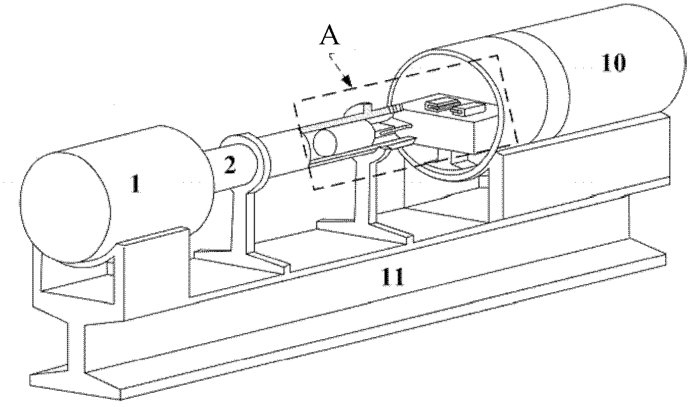
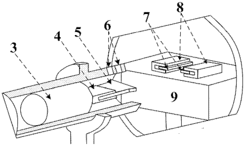
[0042] Such as figure 1 , 2 As shown, a cutter 5 with a thickness of 6 mm, a rake angle of 0°, and a rear angle of 15° is installed on the front end of an aluminum shell 3 with a mass of 1 kg through a cutter holder 4, and placed at the exit of the accelerating barrel 2 , the tool 5 is protruded out of the acceleration barrel 2 so as to adjust the relative position (cutting depth) of the workpiece 7 and the tool 5 .

[0043] The two workpiece clamping and high-precision positioning devices 8 are symmetrically installed on the high-precision lifting platform 9 along the axis of the acceleration barrel, and the distance between the two is guaranteed to be slightly greater than the width of the tool during the installation process. Process two workpieces with a length of 40 mm, a width of 30 mm, and a thickness of 2 mm and install them on the workpiece clamping and high-...

Embodiment 2

[0048] Under the constant situation of keeping parameter in embodiment 1, change the initial position of cannonball 3 in accelerating barrel 2, make its distance from accelerating barrel 2 exit 6 meters, finally can realize the cutting experiment that cutting speed is 85m / s.

Embodiment 3

[0050] Under the condition of keeping the parameters in Example 2 unchanged, the air pressure value of the light air gun 1 was adjusted to 2.5MPa, and finally a cutting experiment with a cutting speed of 160m / s could be realized.


PUM

PropertyMeasurementUnit
Thicknessaaaaaaaaaa

Abstract

The invention discloses a high-speed cutting experiment device based on a light-gas gun loading technique. The high-speed cutting experiment device comprises a light-gas gun power loading mechanism, a cutting mechanism, a fixing mechanism and an arresting mechanism, wherein the light-gas gun power loading mechanism is used for pushing the cutting mechanism to fly along a preset orbit at preset speed; the cutting mechanism is used for cutting a workpiece to be processed at high-speed; the fixing mechanism is used for fixing the workpiece to be processed; the arresting mechanism is used for receiving the cutting mechanism which completes cutting; and the light-gas gun power loading mechanism, the cutting mechanism, the fixing mechanism and the arresting mechanism are sequentially arranged along an axis. By adjusting the air pressure of a light-gas gun, the mass of a bullet or the initial position of the bullet, very wide cutting speed can be obtained; and by using the device for high-speed cutting experiments with cutting speed which reaches 30m / s to 150m / s, the demands of the high-speed cutting experiments of most materials can be met.

Description

technical field [0001] The invention belongs to the field of metal cutting, in particular to a high-speed orthogonal cutting experimental device based on light gas cannon loading technology. Background technique [0002] The manufacturing industry is the pillar industry of my country's national economy, and its added value accounts for more than 40% of my country's gross domestic product (GDP), among which cutting processing accounts for 15% of the total output value of the entire manufacturing industry. Therefore, the development of advanced cutting processing technology is the starting point Leverage for a new upsurge in our economy. High-speed cutting can reduce the cutting force by 30%, and increase the processing efficiency by more than 3 to 5 times. It is known as a technological revolution in the machinery manufacturing industry in the 20th century. The mechanism of high-speed cutting is the theoretical basis for the application and development of high-speed cutting t...

Claims


Application Information

Patent Timeline
IPC IPC(8): G01N3/58
Inventor 戴兰宏马维叶贵根凌中蒋敏强
Owner INST OF MECHANICS - CHINESE ACAD OF SCI
Why Eureka
Eureka Blog
Learn More