Electronic equipment with camera and flash lamp

A technology of electronic equipment and flashlight, which is applied in television, optics, photography, etc., can solve the problems of not being able to adjust the height of the two-function accessories on the same plane, and wasting the internal space of the POS machine, so as to achieve the effect of reducing the occupied space

Active Publication Date: 2012-07-04
FUJIAN LANDI COMML EQUIP CO LTD
View PDF6 Cites 10 Cited by
  • Summary
  • Abstract
  • Description
  • Claims
  • Application Information

AI Technical Summary

Problems solved by technology

[0003] In the present POS machine, all have flashlight and camera function, it generally adopts two flat wires to connect two rigid circuit boards to connect flashlight and camera respectively, and it has wasted the space inside the POS machine, and the electronic equipment of prior art, making It is getting more and more refined, and the overall development is small and fine, and it is necessary to save all the space that can be saved. Moreover, the two rigid circuit boards control the flash and the camera respectively, so that the consistency of these two functional accessories is not good enough to achieve simultaneous synchronization. , the use of rigid circuit boards cannot flexibly adjust the height of the surface of the two functional accessories, so that the surfaces of the two functional accessories cannot be on the same plane. After assembly, the housing needs to consider the height of the two functional accessories to set the suitable shell , the surface of the shell is not flat, and it cannot maintain balance when moving and placing it, and it is impossible to accurately grasp the corresponding height of the camera and flash when holding it

Method used


Image

  • Electronic equipment with camera and flash lamp
  • Electronic equipment with camera and flash lamp
  • Electronic equipment with camera and flash lamp

Examples


Embodiment Construction

[0019] In order to describe the technical content, structural features, achieved goals and effects of the present invention in detail, the following will be described in detail in conjunction with the embodiments and accompanying drawings.

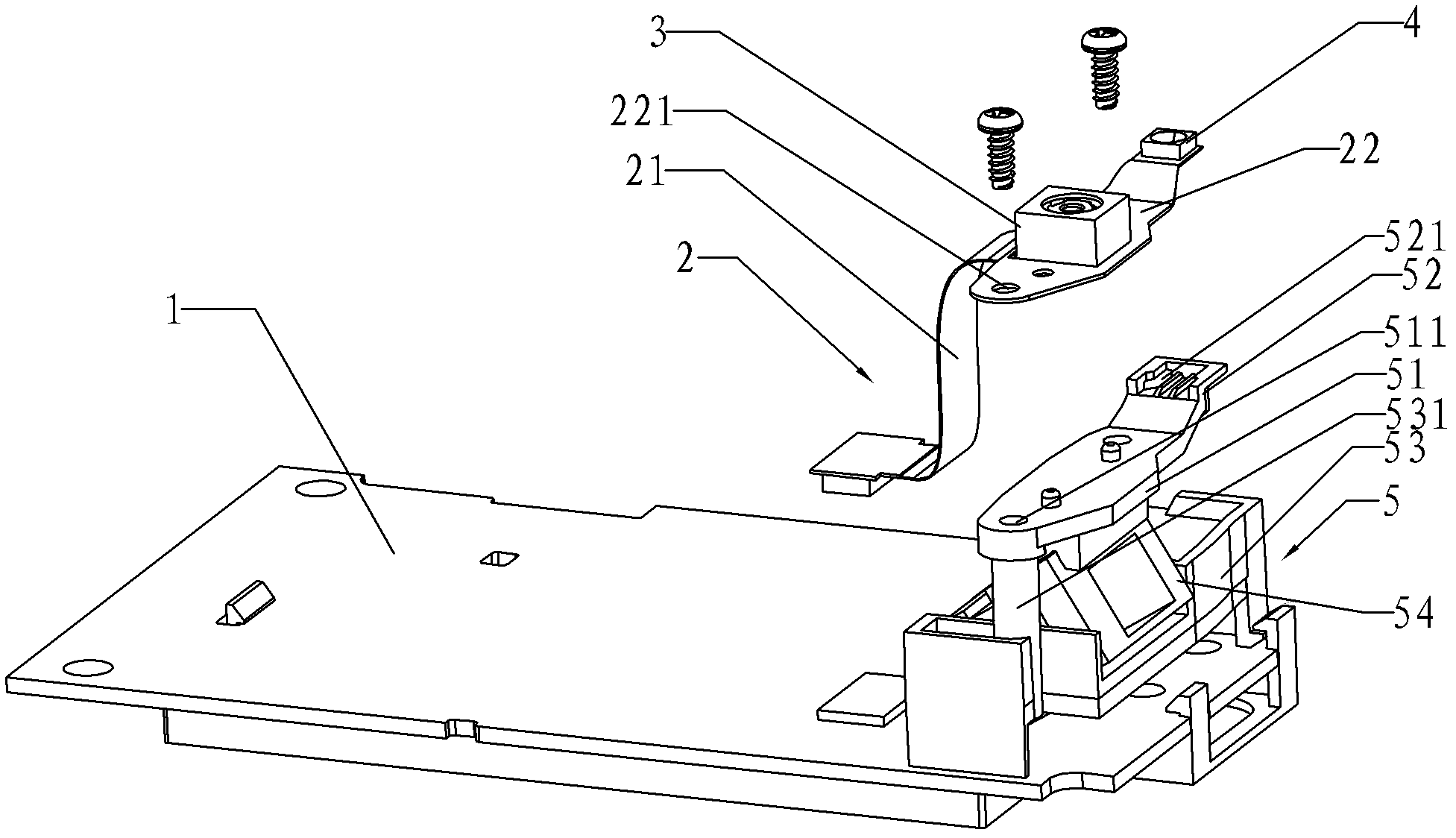
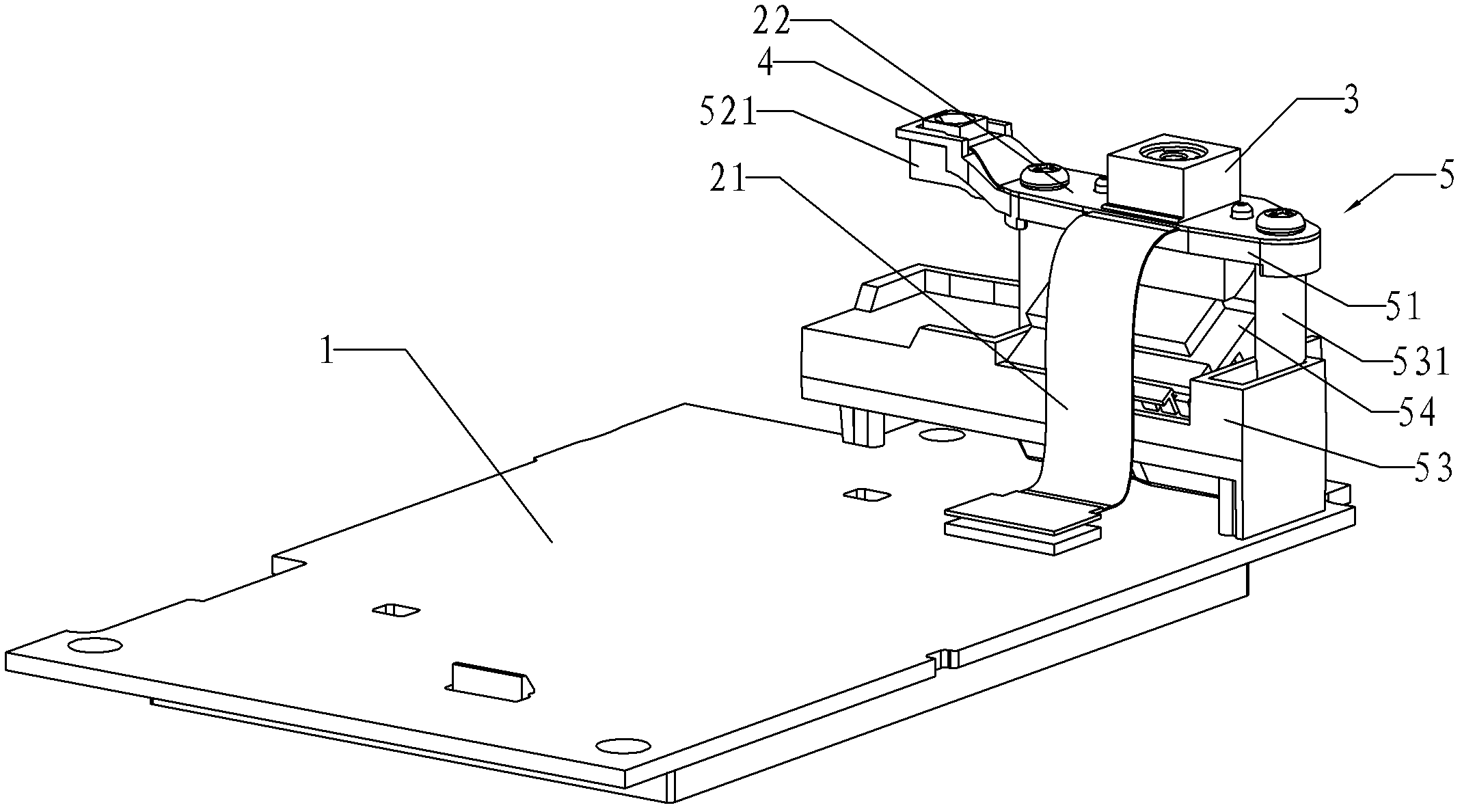
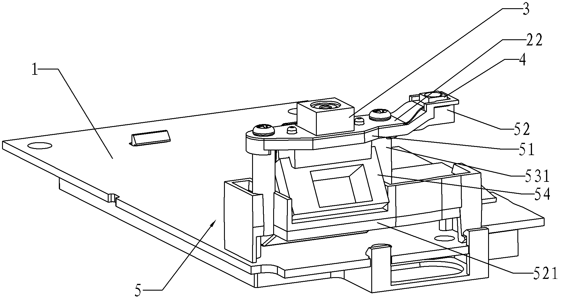
[0020] Please refer to the attached figure 1 , attached figure 2 and attached image 3 As shown in the drawings, this embodiment provides an electronic device with a camera 3 and a flash 4, including a housing, a control circuit board 1 matched with the housing, and a flexible circuit board 2, which includes a connecting part 21 and operating part 22, the connecting part 21 is connected with the control circuit board 1, the main circuit is arranged on the operating part 22, the camera 3 and the flashlight 4 are arranged on the operating part 22, and the control circuit board 1 is installed with Functional accessory 5, the operating part 22 of the flexible circuit board 2 is fixed on the top plate of the functional accessory 5, the top p...


PUM


Abstract

The invention relates to electronic equipment with a camera and a flash lamp, which comprises a shell, a control circuit board and a flexible circuit board, wherein the control circuit board is matched with the shell to be arranged; the flexible circuit board comprises a connecting part and an operating part; the connecting part is connected with the control circuit board; a main circuit is arranged on the operating part; the camera and the flash lamp are arranged on the operating part; a functional fitting is arranged on the control circuit board; the operating part of the flexible circuit board is fixed on a top plate of the functional fitting; the top plate of the functional fitting comprises a horizontal crossarm and a boss; the position of the boss corresponds to the position of the flash lamp; a groove for the flash lamp to transversely slide is arranged on the boss; after sliding into the groove, the flash lamp is fixed on the boss; and the top surface of the fixed flash lamp and the top surface of the camera are positioned on the same plane. The invention aims to provide the electronic equipment with the camera and the flash lamp, which has the advantages that the camera and the flash lamp have good consistency; the electronic equipment has a simple integral structure; and the inner space of the electronic equipment is effectively utilized.

Description

technical field [0001] The invention relates to the field of electronic products, in particular to an electronic device with a camera and a flashlight. Background technique [0002] In electronic products, it is usually necessary to set many functional mechanisms to achieve or expand the functions of the electronic equipment. Taking the point of sale machine (hereinafter referred to as POS machine) as an example, POS refers to the computerized transaction system used in automated supermarkets, which uses scanners to read labels and barcodes, electronic cash registers, and other special equipment To record the revenue of the point of sale, the POS machine refers to the terminal used in this process. [0003] In the present POS machine, all have flashlight and camera function, it generally adopts two flat wires to connect two rigid circuit boards to connect flashlight and camera respectively, and it has wasted the space inside the POS machine, and the electronic equipment of ...

Claims


Application Information

Patent Timeline
Patent Type & Authority Applications(China)
IPC IPC(8): G07G1/12H04N5/225G03B15/05G03B30/00
Inventor 潘永魁翁光云
Owner FUJIAN LANDI COMML EQUIP CO LTD
Why Eureka
Try Eureka