

Battery active material, nonaqueous electrolyte battery and battery pack
A non-aqueous electrolyte and active material technology, applied in non-aqueous electrolyte batteries, active material electrodes, battery electrodes, etc., can solve problems such as capacity reduction
- Summary
- Abstract
- Description
- Claims
- Application Information
AI Technical Summary
Problems solved by technology
Method used
Image

Examples
no. 1 Embodiment approach
[0024] The battery active material of the first embodiment can be used in a nonaqueous electrolyte secondary battery. The active substance contains the formula Li x Ti 1-y M1 y Nb 2-z M2 z o 7+δ A monoclinic composite oxide represented by (0≤x≤5, 0≤y≤1, 0≤z≤2, -0.3≤δ≤0.3). In the formula, the M1 is at least one selected from Zr, Si and Sn, and the M2 is at least one selected from V, Ta and Bi.
[0025] Such a monoclinic composite oxide has 1.5 V (vs. Li / Li + ) around the lithium intercalation potential, therefore, can be stably repeated rapid charge and discharge.
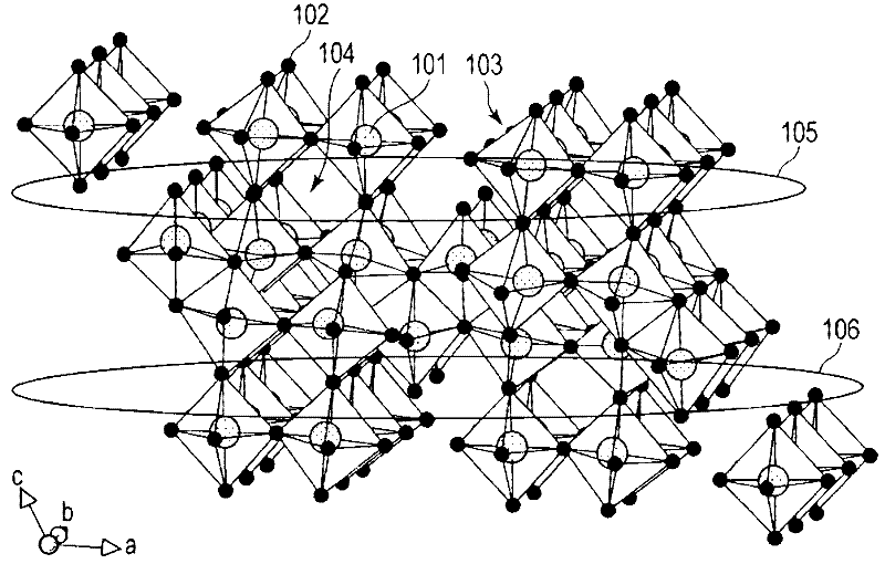
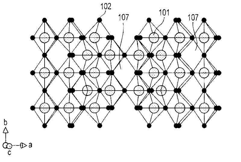
[0026] as formula Li x Ti 1-y M1 y Nb 2-z M2 z o 7+δ Examples of monoclinic composite oxides shown include monoclinic TiNb 2 o 7 . figure 1 and figure 2 A schematic diagram of its crystal structure is shown in .
[0027] Such as figure 1 As shown, in the monoclinic TiNb 2 o 7 In the crystal structure of , metal ions 101 and oxide ions 102 constitute a skeleton structure 103 . In addition, as ...
no. 2 Embodiment approach
[0059] In the second embodiment, there is provided a non-aqueous electrolyte battery including: a negative electrode containing the battery active material in the first embodiment, a positive electrode, a non-aqueous electrolyte, a separator, and an outer packaging member.
[0060] Hereinafter, the negative electrode, the positive electrode, the non-aqueous electrolyte, the separator, and the exterior member will be described in detail.
[0061] 1) Negative electrode
[0062] The negative electrode includes a current collector and a negative electrode layer (a layer containing a negative electrode active material). The negative electrode layer is formed on one or both surfaces of the current collector, and contains an active material, an optional conductive agent, and a binder.
[0063] As the negative electrode active material, the formula Li described in the first embodiment can be used x Ti 1-y M1 y Nb 2-z M2 z o 7+δ A monoclinic composite oxide represented by (0≤x≤5...
no. 3 Embodiment approach
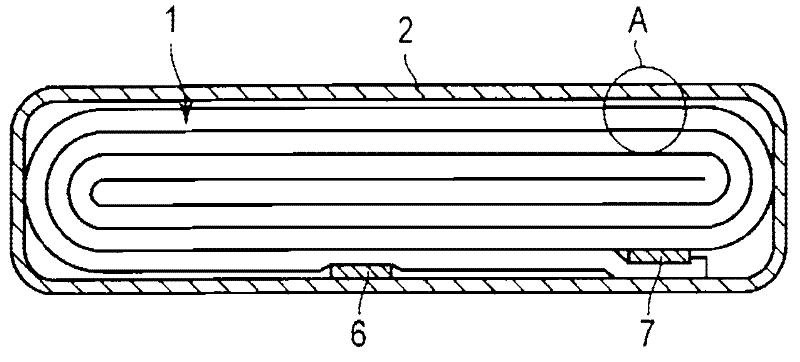
[0116] Next, a battery pack according to a third embodiment will be described with reference to the drawings. The battery pack includes one or more nonaqueous electrolyte batteries (single cells) according to the second embodiment described above. When a plurality of cells are included, the cells are arranged by being electrically connected in series or in parallel.
[0117] Figure 7 and Figure 8 An example of the battery pack 20 is shown in . The battery pack 20 contains multiple image 3 A flat battery 21 of the structure shown. Figure 7 is an exploded perspective view of the battery pack 20, Figure 8 yes means Figure 7 A block diagram of the electrical circuit of the battery pack 20.
[0118] The plurality of single cells 21 are stacked so that the negative terminal 6 and the positive terminal 7 extending outward are directed in the same direction, and are bound with an adhesive tape 22 to form a battery pack 23 . These cells 21 as Figure 8 The shown mutuals ...
PUM
| Property | Measurement | Unit |
|---|---|---|
| Diameter | aaaaa | aaaaa |
| Thickness | aaaaa | aaaaa |
| Thickness | aaaaa | aaaaa |
Abstract
Description
Claims
Application Information