Methods for passing through and assisting in passing through network isolation equipment in Internet protocol (IP) monitoring system, and node

A technology for monitoring nodes and network isolation, which is applied in transmission systems, electrical components, etc., and can solve problems such as hidden dangers in enterprise intranet security

Active Publication Date: 2012-07-04
ZHEJIANG UNIVIEW TECH CO LTD
View PDF2 Cites 18 Cited by
  • Summary
  • Abstract
  • Description
  • Claims
  • Application Information

AI Technical Summary

Problems solved by technology

This brings security ri...

Method used


Image

  • Methods for passing through and assisting in passing through network isolation equipment in Internet protocol (IP) monitoring system, and node
  • Methods for passing through and assisting in passing through network isolation equipment in Internet protocol (IP) monitoring system, and node
  • Methods for passing through and assisting in passing through network isolation equipment in Internet protocol (IP) monitoring system, and node

Examples


Embodiment 1

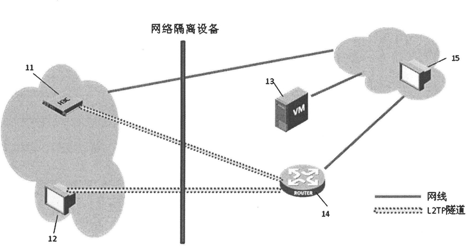
[0034] figure 1 A schematic network diagram of Embodiment 1 is shown. The network is an IP surveillance system. The IP monitoring system includes multiple monitoring nodes. figure 1 , the monitoring node EC11 is isolated from another network by a network isolation device. The network isolation device can be NAT, firewall or gatekeeper. In this example, if figure 1 , the network where the monitoring node EC11 in the monitoring system is located is the network inside the network isolation device, which is called network A here, which is isolated or protected by the network isolation device, and the network outside the network isolation device is called network B here. Due to the existence of the network isolation device, network A can access network B, but network B cannot access network A without special configuration. The IP surveillance system also includes an L2TP relay 14 . The IP address of the monitoring node EC11 itself is 10.10.10.10, that is, the IP address belon...

Embodiment 2

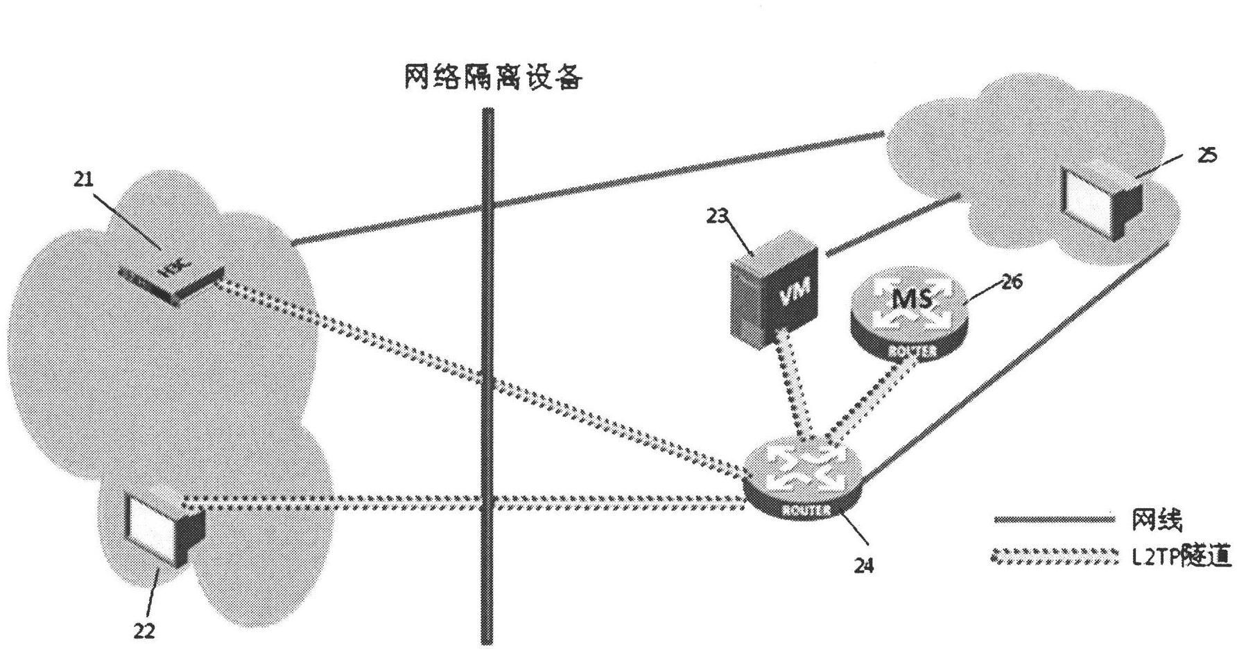
[0042] figure 2 A schematic diagram of the network of the second embodiment is shown. figure 2 network diagram and figure 1 The difference is that the L2TP relay 24 in network B initiates a tunnel connection request to VM23 to establish an L2TP tunnel connection with VM23; network B also includes an MS26, and the L2TP relay 24 also initiates a tunnel connection request to MS26 to establish an L2TP tunnel connection with MS26. The L2TP relay 24 also initiates a tunnel connection request to the monitoring node EC21 in the network A to establish an L2TP tunnel connection with EC21. The IP address allocated by EC21, VM23, and MS26 to L2TP relay 24 can be an IP address in an independent address pool, that is, the IP address in the address pool can plan an IP address segment separately, and does not need to occupy the IP address planned by network B, for example EC21 allocates addresses in 14.14.14.0 / 24, VM23 allocates addresses in 15.15.10.0 / 24, MS26 allocates addresses in 16.1...

Embodiment 3

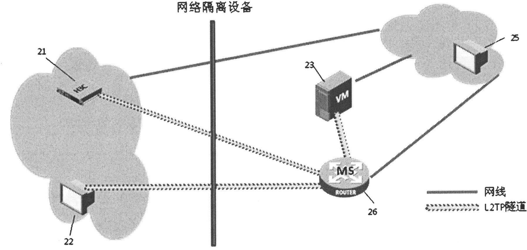
[0049] image 3 A schematic diagram of the network of Embodiment 3 is shown. exist image 3 Among them, the IP monitoring system includes a monitoring node VM31, and the monitoring node VM31 is isolated from another network by a network isolation device. The network isolation device can be NAT, firewall or gatekeeper. The network where the monitoring node EC11 in the monitoring system is located is the network inside the network isolation device, called network A, which is isolated or protected by the network isolation device; the network outside the network isolation device is called network B. Due to the existence of the network isolation device, network A can access network B, but network B cannot access network A without special configuration. The IP monitoring system also includes an L2TP relay device 33 . The IP address of the monitoring node VM31 itself, that is, the IP address belonging to the network A is 10.10.10.10. The IP address of the L2TP relay device 33 itse...


PUM


Abstract

The invention discloses a method for passing through network isolation equipment in an Internet protocol (IP) monitoring system. The method comprises the following steps that: a first monitoring node in an inner network of the network isolation equipment serves as a layer 2 tunneling protocol network server (LNS), and receives a tunnel connection request initiated by a layer 2 tunneling protocol (L2TP) relay which serves as an L2TP access concentrator (LAC); after L2TP tunnel connection is established, the first monitoring node allocates an IP address to the L2TP relay, and activates the IP address of own L2TP virtual interface; the first monitoring node receives a tunnel message from the L2TP relay, decapsulates the tunnel message to obtain an inner-layer IP message with the content of monitoring signaling data, acquires the monitoring signaling data from the inner-layer IP message, and performs corresponding signaling processing; and the first monitoring node encapsulates own generated monitoring signaling data into the inner-layer IP message, encapsulates the inner-layer IP message into the tunnel message, and transmits the tunnel message to the L2TP relay. By the method, the monitoring node can simply and effectively pass through the isolation equipment, and the interference of the isolation equipment in a monitoring service is avoided.

Description

technical field [0001] The invention relates to the field of video monitoring, in particular to a method and node for traversing and assisting traversing network isolation devices in an IP monitoring system. Background technique [0002] IP network-based video surveillance has gradually developed into a mainstream solution in the security industry, and has been successfully applied to large-scale projects such as safety projects, highways, public security networks, and parks. The standardization and openness of IP also make it easy to integrate various network islands and make it easy to expand the network scale. Considering the shortage of IPv4 address resources and the reality that the existing regional network address segments overlap with each other, as well as the needs of various network security, NAT, firewalls, security isolation gatekeepers and other devices are widely used in large-scale networks. This makes the signaling and business processes of the IP-based vid...

Claims


Application Information

Patent Timeline
IPC IPC(8): H04L29/06H04L29/08
Inventor 周迪王连朝
Owner ZHEJIANG UNIVIEW TECH CO LTD
Why Eureka
Try Eureka