Trap printing method and system based on boundary

A boundary and trapping technology, applied in the direction of image communication, electrical components, etc., can solve the problems of blunt trapping results, no consideration of the original image structure information, and large damage to image information.

Inactive Publication Date: 2012-07-04
PEKING UNIV +1
View PDF4 Cites 5 Cited by
  • Summary
  • Abstract
  • Description
  • Claims
  • Application Information

AI Technical Summary

Problems solved by technology

This method does not take into account the structural information of the original image, which greatly damages the imag

Method used


Image

  • Trap printing method and system based on boundary
  • Trap printing method and system based on boundary
  • Trap printing method and system based on boundary

Examples


Embodiment Construction

[0078] The present invention will be described in detail below in conjunction with specific embodiments and accompanying drawings.

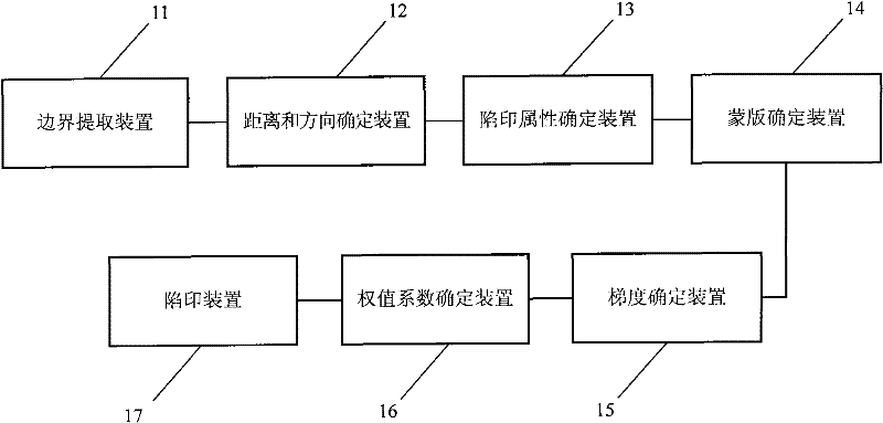
[0079] figure 1 The structure of the boundary-based trapping system in this embodiment is shown. Such as figure 1 As shown, the system includes a boundary extraction device 11, a distance and direction determination device 12 connected with the boundary extraction device 11, a trap attribute determination device 13 connected with the distance and direction determination device 12, and a trap attribute determination device 13 connected with the trap attribute determination device 13 A mask determining device 14 , a gradient determining device 15 connected to the mask determining device 14 , a weight coefficient determining device 16 connected to the gradient determining device 15 , and a trapping device 17 connected to the weight coefficient determining device 16 .

[0080] The boundary extracting device 11 is used for extracting the boundary in...


PUM


Abstract

The invention relates to a trap printing method and system based on a boundary and belongs to the technical field of trap printing. The trap printing method comprises the following steps of: firstly, extracting the boundary of an image to be subjected to the trap printing; determining the distance and direction from each pixel point within a pre-set width range T1 at two sides of the boundary to the boundary which is closest to the pixel point; and then, determining trap printing attributes of the boundary and color channels at two sides of the boundary; and then, determining the gradient amplitude and direction of the pixel point needing to be subjected to the trap printing; determining weight coefficients of the adjacent pixel points in a trap printing template according to the gradient amplitude and direction of a central pixel point; and finally, carrying out the trap printing on the pixel point needing to be subjected to the trap printing through the trap printing template. According to the invention, structural information of an original image can be maintained as much as possible and the trap printing quality of the image is improved.

Description

technical field [0001] The invention belongs to the technical field of trapping in image processing, and in particular relates to a border-based trapping method and system. Background technique [0002] Trapping is also called trapping, also known as scaling, mainly to make up for the gap between two adjacent different colors caused by inaccurate printing overprint. Currently there are two main types of trapping methods: trapping methods based on neighborhood (such as Photoshop image trapping) and trapping methods based on boundaries. [0003] The trapping method based on the neighborhood is to analyze the neighborhood point by point of the whole image, and calculate the trapping value according to the color information in the neighborhood of the point. This trapping method is too sensitive and changes many subtle parts inside the natural image, which is actually unnecessary and causes great damage to the image. Generally speaking, it is only desired to trap the junction b...

Claims


Application Information

Patent Timeline
IPC IPC(8): H04N1/58
Inventor 张宏志袁梦尤李平立杨文鲜
Owner PEKING UNIV
Why Eureka
Try Eureka