Eureka AIR delivers breakthrough ideas for toughest innovation challenges, trusted by R&D personnel around the world.

Multi-path interference correction method and system for TOF (Time of Flight) module and electronic equipment

A multi-path interference and correction method technology, applied in the field of TOF, can solve the problems of changing the hardware of the module, time-consuming, and increasing the complexity of the module structure, etc.

Pending Publication Date: 2021-06-22
SUNNY OPTICAL ZHEJIANG RES INST CO LTD
View PDF7 Cites 1 Cited by
  • Summary
  • Abstract
  • Description
  • Claims
  • Application Information

AI Technical Summary

Problems solved by technology

[0004] However, for the first solution, changing the hardware of the TOF module will greatly increase the complexity of the module structure and increase the manufacturing cost of the module; especially for the TOF module that has been shipped, it is impossible to change the hardware of the module Achieved
For the second solution, if the measurement deviation (error) is directly solved by establishing an optical signal propagation simulation model to correct multipath interference, it will take a long time due to the huge amount of calculation in the solution process, which will cause this problem. However, this method cannot meet the real-time application requirements of the TOF module; and if an autoencoder model is established, a set of appropriate features based on the representation of the depth image that is interfered by multipath is first learned through the encoder, and then the trained decoder is used to learn from the If a depth map without multipath interference is restored from a depth map with multipath interference, the error distribution of multipath interference will be learned directly and violently, resulting in the restored depth map not retaining the original structural information.

Method used


Image

  • Multi-path interference correction method and system for TOF (Time of Flight) module and electronic equipment
  • Multi-path interference correction method and system for TOF (Time of Flight) module and electronic equipment
  • Multi-path interference correction method and system for TOF (Time of Flight) module and electronic equipment

Examples


Embodiment Construction

[0067] The following description serves to disclose the present invention to enable those skilled in the art to carry out the present invention. The preferred embodiments described below are only examples, and those skilled in the art can devise other obvious variations. The basic principles of the present invention defined in the following description can be applied to other embodiments, variations, improvements, equivalents and other technical solutions without departing from the spirit and scope of the present invention.

[0068] In the present invention, the term "a" in the claims and the specification should be understood as "one or more", that is, in one embodiment, the number of an element may be one, while in another embodiment, the number of the element Can be multiple. Unless it is clearly indicated in the disclosure of the present invention that there is only one element, the term "a" cannot be understood as unique or single, and the term "a" cannot be understood a...


PUM


Abstract

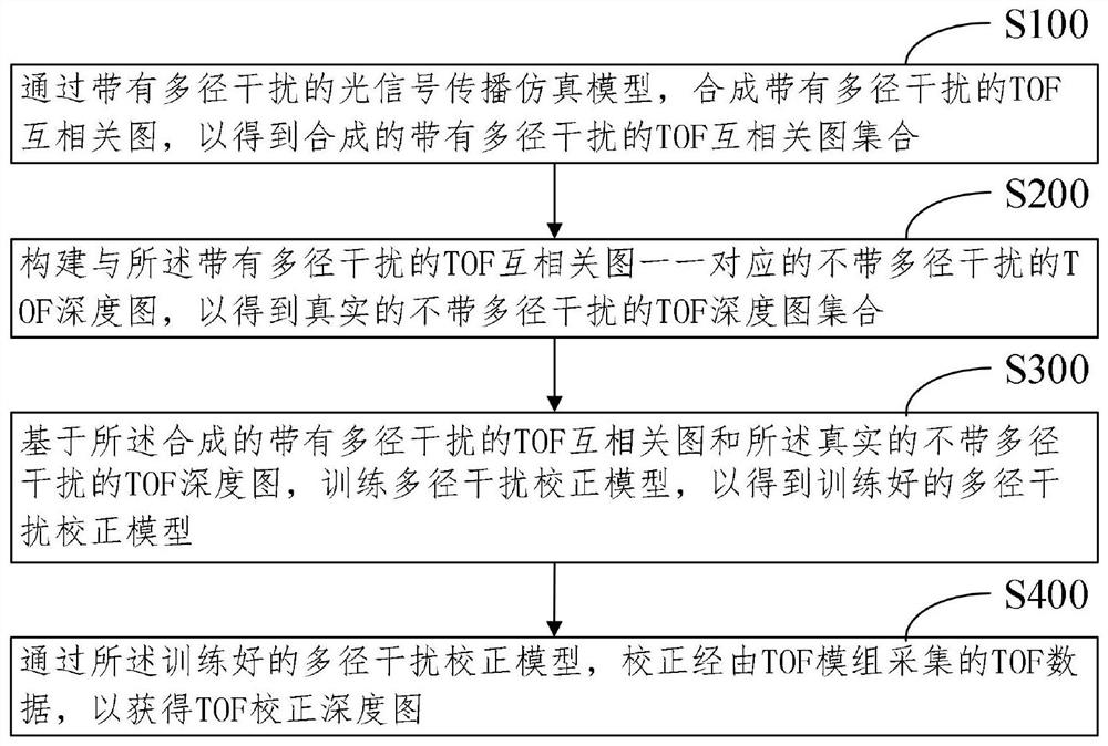
The invention discloses a multi-path interference correction method and system for a TOF (Time of Flight) module and electronic equipment. The multi-path interference correction method for the TOF module comprises the following steps: synthesizing a TOF cross-correlation graph with multi-path interference through an optical signal propagation simulation model with multi-path interference so as to obtain a synthesized TOF cross-correlation graph set with multi-path interference; constructing TOF depth maps which are in one-to-one correspondence with the TOF cross-correlation maps with the multi-path interference and do not have the multi-path interference, so as to obtain a real TOF depth map set without the multi-path interference; training a multi-path interference correction model based on the synthesized TOF cross-correlation graph set with the multi-path interference and the real TOF depth graph set without the multi-path interference to obtain a trained multi-path interference correction model; and correcting TOF data collected by a TOF module through the trained multipath interference correction model to obtain a TOF corrected depth map.

Description

technical field [0001] The invention relates to the technical field of TOF, in particular to a method for correcting multipath interference for a TOF module, a system thereof and electronic equipment. Background technique [0002] TOF (Time of flight, time of flight) technology is one of the most outstanding optical measurement technologies. It can be applied to the fields of robots / drones, somatosensory entertainment, monitoring and security, and smart logistics. It is one of the research hotspots in recent years. The TOF module is one of the main members of the current 3D depth camera. Its principle is to continuously send light pulses (generally invisible light) to the measured object through the transmitter, and then use the sensor to receive the light pulses reflected from the measured object. Furthermore, the distance between the measured object and the camera is obtained through the flight (round-trip) time of the light pulse. Since the premise of the TOF depth measu...

Claims


Application Information

Patent Timeline
IPC IPC(8): G01S17/894G01S17/08G01S7/497G06K9/62G06T5/00G06T7/50G06T17/00
CPCG01S17/89G01S17/08G01S7/497G06T7/50G06T17/00G06F18/214G06T5/80Y02D30/70
Inventor 汲梦宇田文军蒋坤君胡增新
Owner SUNNY OPTICAL ZHEJIANG RES INST CO LTD
Why Eureka
Eureka Blog
Learn More